AGV XC AGV XC DMS
|
|
|
- Krista Vīksna
- pirms 4 gadiem
- Skatījumi:
Transkripts

1 AGV XC AGV XC DMS Original instructions Originalbetriebsanleitung Notice originale Istruzioni originali Manual original Oorspronkelijke gebruiksaanwijzing Original brugsanvisning Original bruksanvisning Bruksanvisning i original Alkuperäiset ohjeet Πρωτότυπο οδηγιών χρήσης Orijinal işletme talimatı Původním návodem k používání Pôvodný návod na použitie Instrukcją oryginalną Eredeti használati utasítás Izvirna navodila Originalne pogonske upute Instrukcijām oriģinālvalodā Originali instrukcija Algupärane kasutusjuhend Оригинальное руководство по эксплуатации Оригинално ръководство за експлоатация Instrucţiuni de folosire originale Оригинален прирачник за работа Оригінал інструкції з експлуатації
2 ENGLISH DEUTSCH FRANÇAIS ITALIANO ESPAÑOL PORTUGUES NEDERLANDS DANSK NORSK SVENSKA SUOMI ΕΛΛΗΝΙΚΑ TÜRKÇE ČESKY SLOVENSKY POLSKI MAGYAR SLOVENSKO HRVATSKI LATVISKI LIETUVIŠKAI EESTI РУССКИЙ ÁÚËÃÀÐÑÊÈ ROMÂNIA Picture section with operating description and functional description Bildteil mit Anwendungs- und Funktionsbeschreibungen Partie imagée avec description des applications et des fonctions Sezione illustrata con descrizione dell'applicazione e delle funzioni Sección de ilustraciones con descripción de aplicación y descripción funcional Parte com imagens explicativas contendo descrição operacional e funcional Beeldgedeelte met toepassings- en functiebeschrijvingen Billeddel med anvendelses- og funktionsbeskrivelser Bildedel med bruks- og funksjonsbeskrivelse Bilddel med användnings- och funktionsbeskrivning Kuvasivut käyttö- ja toimintakuvaukset Τμήμα εικόνων με περιγραφές χρήσης και λειτουργίας Resim bölümü Uygulama ve fonksiyon açıklamaları ile birlikte Obrazová část s popisem aplikací a funkcí Text section with Technical Data, important Safety and Working Hints and description of Symbols Textteil mit Technischen Daten, wichtigen Sicherheits- und Arbeitshinweisen und Erklärung der Symbole. Partie textuelle avec les données techniques, les consignes importantes de sécurité et de travail ainsi que l explication des pictogrammes. Sezione testo con dati tecnici, importanti informazioni sulla sicurezza e sull utilizzo, spiegazione dei simboli. Sección de texto con datos técnicos, indicaciones importantes de seguridad y trabajo y explicación de los símbolos. Parte com texto explicativo contendo Especifi cações técnicas, Avisos de segurança e de operação e a Descrição dos símbolos. Tekstgedeelte met technische gegevens, belangrijke veiligheids- en arbeidsinstructies en verklaring van de symbolen. Tekstdel med tekniske data, vigtige sikkerheds- og arbejdsanvisninger og symbolforklaring. Tekstdel med tekniske data, viktige sikkerhets- og arbeidsinstruksjoner og forklaring av symbolene. Textdel med tekniska informationer, viktiga säkerhets- och användningsinstruktioner samt symbolförklaringar. Tekstisivut: tekniset tiedot, tärkeät turvallisuus- ja työskentelyohjeet sekä merkkien selitykset. Τμήμα κειμένου με τεχνικά χαρακτηριστικά, σημαντικές υποδείξεις ασφαλείας και εργασίας και εξήγηση των συμβόλων. Teknik bilgileri, önemli güvenlik ve çalışma açıklamalarını ve de sembollerin açıklamalarını içeren metin bölümü. Textová část s technickými daty, důležitými bezpečnostními a pracovními pokyny a s vysvětlivkami symbolů Obrazová časťs popisom aplikácií a funkcií Textová časť s technickými dátami, dôležitými bezpečnostnými a pracovnými pokynmi a s vysvetlivkami symbolov Część rysunkowa z opisami zastosowania i działania Część opisowa z danymi technicznymi, ważnymi wskazówkami dotyczącymi bezpieczeństwa i pracy oraz objaśnieniami symboli Képes részalkalmazási- és működési leírásokkal Szöveges rész műszaki adatokkal, fontos biztonsági- és munkavégzési útmutatásokkal, valamint a szimbólumok magyarázata Del slikez opisom uporabe in funkcij Del besedila s tehničnimi podatki, pomembnimi varnostnimi opozorili in delovnimi navodili in pojasnili simbolov Dio sa slikamasa opisima primjene i funkcija Dio štiva sa tehničkim podacima, važnim sigurnosnim i radnim uputama i objašnjenjem simbola Attēla daļa ar lietošanas un funkciju aprakstiem Teksta daļa ar tehniskajiem parametriem, svarīgiem drošības un darbības norādījumiem, simbolu atšifrējumiem Paveikslėlio dalissu vartojimo instrukcija ir funkcijų aprašymais Teksto dalis su techniniais duomenimis, svarbiomis saugumo ir darbo instrukcijomis bei simbolių paaiškinimais Pildiosa kasutusjuhendi ja funktsioonide kirjeldusega Tekstiosa tehniliste näitajate, oluliste ohutus- ja tööjuhenditega ning sümbolite kirjeldustega Раздел иллюстрацийс описанием эксплуатации и функций Текстовый раздел, включающий технические данные, важные рекомендации по безопасности и эксплуатации, а также описание используемых символов Част със снимки с описания за приложение и функции Част с текст с технически данни, важни указания за безопасност и работа и разяснение на символите Secvenţa de imagine cu descrierea utilizării şi a funcţionării Porţiune de text cu date tehnice, indicaţii importante privind siguranţa şi modul de lucru şi descrierea simbolurilor. МАКЕДОНСКИ Дел со сликисо описи за употреба и функционирање 4 Текстуален дел со Технички карактеристики, важни безбедносни и работни упатства и објаснување на симболите. УКРАЇНСЬКА Частина з зображеннями з описом робіт та функцій Текстова частина з технічними даними, важливими вказівками з техніки безпеки та експлуатації і поясненням символів


3 9 14 SERVICE START STOP

4

5 A 0 1 B C

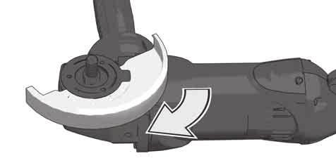
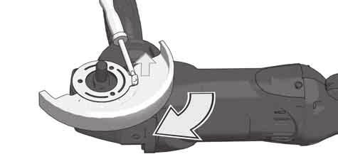
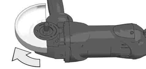
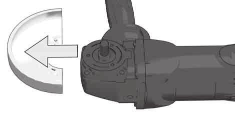
6


7 START START Switch can be locked Schalter ist arretierbar Le commutateur peut être verrouillé L interruttore si può bloccare El interruptor se puede bloquear. O interruptor pode ser bloqueado Schakelaar is vastzetbaar Afbryder kan fikseres Bryter kan låses Brytaren kan arreteras. Katkaisimen voi lukita. Ο διακόπτης μπορεί να ασφαλιστεί Şalter ayarlanabilir Vypínač je aretovatelný Vypínač je aretovateľný Przełącznik daje się zablokować A kapcsoló rögzíthető Stikalo je nastavljivo Prekidač se može aretirati Slēdzis ir labojams Jungiklis gali būti užblokuojamas Lüliti on fikseeritav Фиксируемый переключатель Превключвателят може да се фиксира Comutatorul poate fi blocat Прекинувачот може да се заклучи Вимикач може блокуватися STOP Switch cannot be locked Schalter ist nicht arretierbar Le commutateur ne peut pas être verrouillé L interruttore non si può bloccare El interruptor no se puede bloquear. O interruptor não pode ser bloqueado Schakelaar is niet vastzetbaar Afbryder kan ikke fikseres Bryter kan ikke låses Brytaren kan inte arreteras. Katkaisinta ei voi lukita. Ο διακόπτης δεν μπορεί να ασφαλιστεί Şalter ayarlanamaz Vypínač není aretovatelný Vypínač je nie aretovateľný Przełącznik nie daje się zablokować A kapcsoló nem rögzíthető Stikalo ni nastavljivo Prekidač se ne može aretirati Slēdzis nav labojams Jungiklis negali būti užblokuojamas Lüliti ei ole fikseeritav Нефиксируемый переключатель Превключвателят не може да се фиксира Comutatorul nu poate fi blocat Прекинувачот не може да се заклуч Вимикач не блокується STOP STOP


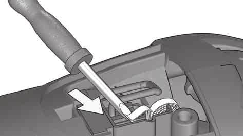
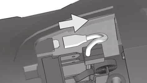
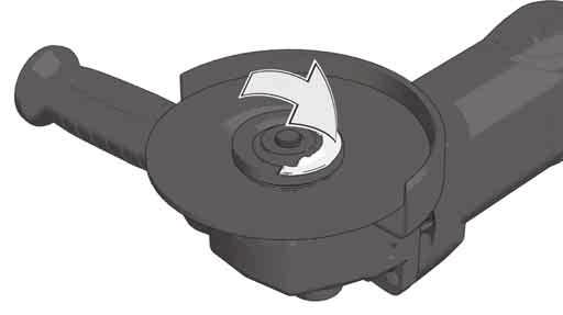
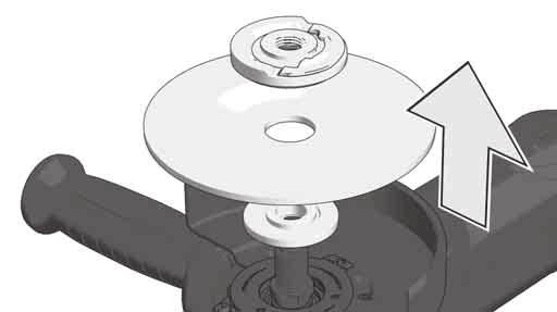
8 SERVICE 1 5 2!

9 <
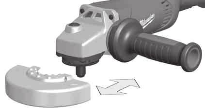
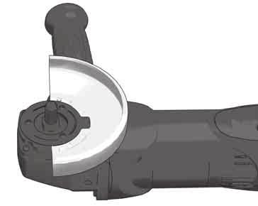
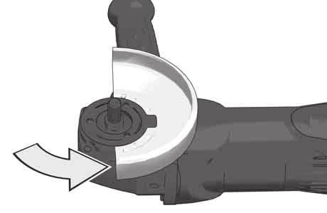
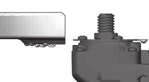
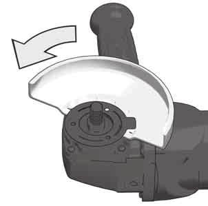
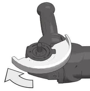
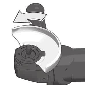
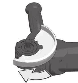
10 TECHNICAL DATA AGV XC AGV XC DMS Angle Grinder Production code Rated input 1750 W 1750 W Rated speed min min -1 D=Grinding disk diameter max. d=grinding disk hole diameter b=grinding disk thickness max.. 6 mm (1/4") 6 mm (1/4") b=cutting disk thickness min. / max. 1,0 / 3 mm 1,0 / 3 mm D=Grinding surface diameter max. D=Wiring brush diameter max. 75 mm 75 mm Thread of work spindle M14 M14 Weight according EPTA-Procedure 01/2003 2,8 kg 2,8 kg Noise/Vibration Information Measured values determined according to EN Typically, the A-weighted noise levels of the tool are: Sound pressure level (Uncertainty K=3dB(A)) 86,5 db(a) 86,5 db(a) Sound power level (Uncertainty K=3dB(A)) 97,5 db(a) 97,5 db(a) Wear ear protectors! Vibration total values (triaxial vector sum) determined according to EN Surface grinding: Vibration emission value a h,sg 9,4 m/s 2 9,4 m/s 2 Uncertainty K 1,5 m/s 2 1,5 m/s 2 Sanding Vibration emission value a h, DS Uncertainty K 3,0 m/s 2 1,5 m/s 2 3,0 m/s 2 1,5 m/s 2 For other applications, e.g. Abrasive Cutting-Off Operations or Wire Brushing other vibration values could occur. WARNING The vibration emission level given in this information sheet has been measured in accordance with a standardised test given in EN and may be used to compare one tool with another. It may be used for a preliminary assessment of exposure. The declared vibration emission level represents the main applications of the tool. However if the tool is used for different applications, with different accessories or poorly maintained, the vibration emission may differ. This may significantly increase the exposure level over the total working period. An estimation of the level of exposure to vibration should also take into account the times when the tool is switched off or when it is running but not actually doing the job. This may signifi cantly reduce the exposure level over the total working period. Identify additional safety measures to protect the operator from the effects of vibration such as: maintain the tool and the accessories, keep the hands warm, organisation of work patterns WARNING! Read all safety warnings and all instructions. Failure to follow the warnings and instructions may result in electric shock, fi re and/or serious injury. Save all warnings and instructions for future reference. ANGLE GRINDER SAFETY WARNINGS Safety Warnings Common for Grinding, Sanding, Wire Brushing or Abrasive Cutting-Off Operations: a) This power tool is intended to function as a grinder, sander, wire brush, or cut-off tool. Read all safety warnings, instructions, illustrations and specifications provided with this power tool. Failure to follow all instructions listed below may result in electric shock, fi re and/or serious injury. b) Operations as polishing are not recommended to be performed with this power tool. Operations for which the power tool was not designed may create a hazard and cause personal injury. c) Do not use accessories which are not specifically designed and recommended by the tool manufacturer. Just because the accessory can be attached to your power tool, it does not assure safe operation. d) The rated speed of the accessory must be at least equal to the maximum speed marked on the power tool. Accessories running faster than their rated speed can break and fl y apart. e) The outside diameter and the thickness of your accessory must be within the capacity rating of your power tool. Incorrectly sized accessories cannot be adequately guarded or controlled. f) The arbour size of wheels, flanges, backing pads or any other accessory must properly fit the spindle of the power tool. Accessories with arbour holes that do not match the mounting hardware of the power tool will run out of balance, vibrate excessively and may cause loss of control. g) Do not use a damaged accessory. Before each use inspect the accessory such as abrasive wheels for chips and cracks, backing pad for cracks, tear or excess wear, wire brush for loose or cracked wires. If power tool or accessory is dropped, inspect for damage or install an undamaged accessory. After inspecting and installing an accessory, position yourself and bystanders away from the plane of the rotating accessory and run the power tool at maximum no-load speed for one minute. Damaged accessories will normally break apart during this test time. h) Wear personal protective equipment. Depending on application, use face shield, safety goggles or safety glasses. As appropriate, wear dust mask, hearing protectors, gloves and shop apron capable of stopping small abrasive or workpiece fragments. The eye protection must be capable of stopping flying debris generated by various operations. The dust mask or respirator must be capable of filtrating particles generated by your operation. Prolonged exposure to high intensity noise may cause hearing loss. i) Keep bystanders a safe distance away from work area. Anyone entering the work area must wear personal protective equipment. Fragments of workpiece or of a broken accessory may fly away and cause injury beyond immediate area of operation. j) Hold power tool by insulated gripping surfaces only, when performing an operation where the cutting tool may contact hidden wiring or its own cord. Cutting accessory contacting a live wire may make exposed metal parts of the power tool live and could give the operator an electric shock. k) Position the cord clear of the spinning accessory. If you lose control, the cord may be cut or snagged and your hand or arm may be pulled into the spinning accessory. l) Never lay the power tool down until the accessory has come to a complete stop. The spinning accessory may grab the surface and pull the power tool out of your control. m) Do not run the power tool while carrying it at your side. Accidental contact with the spinning accessory could snag your clothing, pulling the accessory into your body. n) Regularly clean the power tool s air vents. The motor s fan will draw the dust inside the housing and excessive accumulation of powdered metal may cause electrical hazards. o) Do not operate the power tool near flammable materials. Sparks could ignite these materials. p) Do not use accessories that require liquid coolants. Using water or other liquid coolants may result in electrocution or shock. Kickback and Related Warnings Kickback is a sudden reaction to a pinched or snagged rotating wheel, backing pad, brush or any other accessory. Pinching or snagging causes rapid stalling of the rotating accessory which in turn causes the uncontrolled power tool to be forced in the direction opposite of the accessory s rotation at the point of the binding. For example, if an abrasive wheel is snagged or pinched by the workpiece, the edge of the wheel that is entering into the pinch point can dig into the surface of the material causing the wheel to climb out or kick out. The wheel may either jump toward or away from the operator, depending on direction of the wheel s movement at the point of pinching. Abrasive wheels may also break under these conditions. Kickback is the result of power tool misuse and/or incorrect operating procedures or conditions and can be avoided by taking proper precautions as given below. a) Maintain a firm grip on the power tool and position your body and arm to allow you to resist kickback forces. Always use auxiliary handle, if provided, for maximum control over kickback or torque reaction during start-up. The operator can control torque reactions or kickback forces, if proper precautions are taken. b) Never place your hand near the rotating accessory. Accessory may kickback over your hand. c) Do not position your body in the area where power tool will move if kickback occurs. Kickback will propel the tool in direction opposite to the wheel s movement at the point of snagging. d) Use special care when working corners, sharp edges etc. Avoid bouncing and snagging the accessory. Corners, sharp edges or bouncing have a tendency to snag the rotating accessory and cause loss of control or kickback. e) Do not attach a saw chain, woodcarving blade or toothed saw blade. Such blades create frequent kickback and loss of control. Safety Warnings Specific for Grinding and Abrasive Cutting-Off Operations: a) Use only wheel types that are recommended for your power tool and the specific guard designed for the selected wheel. Wheels for which the power tool was not designed cannot be adequately guarded and are unsafe. b) The guard must be securely attached to the power tool and positioned for maximum safety, so the least amount of wheel is exposed towards the operator. The guard helps to protect operator from broken wheel fragments and accidental contact with wheel and sparks that could ignite clothing. c) Wheels must be used only for recommended applications. For example: do not grind with the side of cut-off wheel. Abrasive cut-off wheels are intended for peripheral grinding, side forces applied to these wheels may cause them to shatter. d) Always use undamaged wheel flanges that are of correct size and shape for your selected wheel. Proper wheel flanges support the wheel thus reducing the possibility of wheel breakage. Flanges for cut-off wheels may be different from grinding wheel flanges. e) Do not use worn down wheels from larger power tools. Wheel intended for larger power tool is not suitable for the higher speed of a smaller tool and may burst. Additional Safety Warnings Specific for Abrasive Cutting-Off Operations: a) Do not jam the cut-off wheel or apply excessive pressure. Do not attempt to make an excessive depth of cut. Overstressing the wheel increases the loading and susceptibility to twisting or binding of the wheel in the cut and the possibility of kickback or wheel breakage. b) Do not position your body in line with and behind the rotating wheel. When the wheel, at the point of operation, is moving away from your body, the possible kickback may propel the spinning wheel and the power tool directly at you. c) When wheel is binding or when interrupting a cut for any reason, switch off the power tool and hold the power tool motionless until the wheel comes to a complete stop. Never attempt to remove the cut-off wheel from the cut while the wheel is in motion otherwise kickback may occur. Investigate and take corrective action to eliminate the cause of wheel binding. d) Do not restart the cutting operation in the workpiece. Let the wheel reach full speed and carefully re-enter the cut. The wheel may bind, walk up or kickback if the power tool is restarted in the workpiece. e) Support panels or any oversized workpiece to minimize the risk of wheel pinching and kickback. Large workpieces tend to sag under their own weight. Supports must be placed under the workpiece near the line of cut and near the edge of the workpiece on both sides of the wheel. f) Use extra caution when making a pocket cut into existing walls or other blind areas. The protruding wheel may cut gas or water pipes, electrical wiring or objects that can cause kickback. Safety Warnings Specific for Sanding Operations: a) Do not use excessively oversized sanding disc paper. Follow manufacturers recommendations, when selecting sanding paper. Larger sanding paper extending beyond the sanding pad presents a laceration hazard and may cause snagging, tearing of the disc or kickback. 18 ENGLISH ENGLISH 19
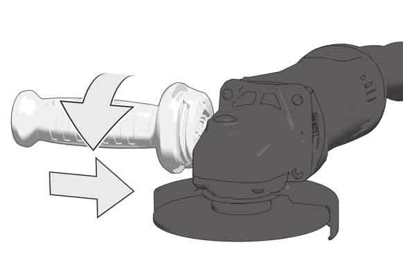
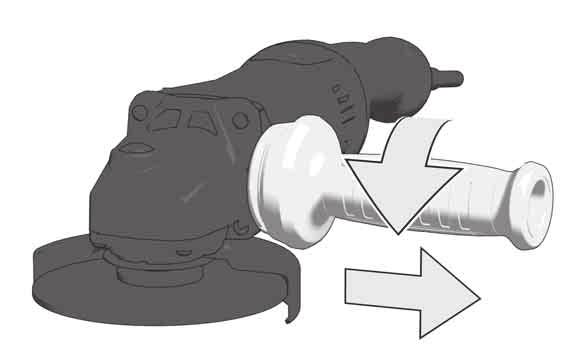
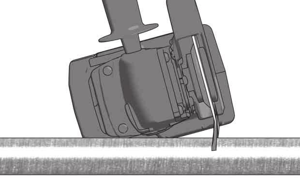
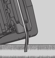
11 Safety Warnings Specific for Wire Brushing Operations: a) Be aware that wire bristles are thrown by the brush even during ordinary operation. Do not overstress the wires by applying excessive load to the brush. The wire bristles can easily penetrate light clothing and/or skin. b) If the use of a guard is recommended for wire brushing, do not allow any interference of the wire wheel or brush with the guard. Wire wheel or brush may expand in diameter due to work load and centrifugal forces. Additional Safety and Working Instructions When grinding metal, fl ying sparks are produced. Take care that no persons are endangered. Because of the danger of fi re, no combustible materials should be located in the vicinity (spark flight zone). Do not use dust extraction. Avoid flying sparks and sanding dust hit your body. Never reach into the danger area of the machine when it is running. Immediately switch off the machine in case of considerable vibrations or if other malfunctions occur. Check the machine in order to find out the cause. Under extreme conditions (e.g. smooth-grinding metals with the arbour and vulcanized fi bre grinding disk), signifi cant contamination can build up on the inside of the angle grinder (metal residue/deposits). For safety reasons, in such conditions a ground fault interrupter must be connected in series. If the ground fault interrupter trips the machine must be sent for service. Sawdust and splinters must not be removed while the machine is running. MAINS CONNECTION Connect only to single-phase AC current and only to the system voltage indicated on the rating plate. It is also possible to connect to sockets without an earthing contact as the design conforms to safety class II. Appliances used at many different locations including wet room and open air must be connected via a residual current device (FI, RCD, PRCD) of 30mA or less. Only plug-in when machine is switched off. Do not let any metal parts reach the airing slots - danger of short circuit! Inrush currents cause short-time voltage drops. Under unfavourable power supply conditions, other equipment may be affected. If the system impedance of the power supply is lower than 0,2 Ohm, disturbances are unlikely to occur. SPECIFIED CONDITIONS OF USE The angle grinder is intended for grinding and cutting metal, stone and ceramic materials as well as sanding and wire brushing. Use the safety guard from the accessories range when performing out cutting work. Please refer to the instructions supplied by the accessory manufacturer The machine is suitable only for working without water. WORKING INSTRUCTIONS For accessories intended to be fi tted with threaded hole wheel, ensure that the thread in the wheel is long enough to accept the spindle length. Always use and store the cutting and grinding disks according to the manufacturer's instructions. Always use the correct guard for cutting and grinding. Always use guard with cutting guide from the accessories range for cutting stone. The grinding surface of the centre depressed wheels must be mounted min. 2 mm below the plane of the guard lip. The adjusting nut must be tightened before starting to work with the machine. Always use the auxiliary handle. The workpiece must be fixed if it is not heavy enough to be steady. Never move the workpiece towards the rotating disk by hand. STARTUP PROTECTION A zero-voltage switch prevents the machine from restarting after a power failure. On resuming work, switch the machine off and then back on again. STARTING CURRENT LIMITER + SMOOTH START The starting current for the machine is several times greater than rated current. The starting current limiter reduces the starting current to such an extent that a fuse (16 A, slow-blow) is not tripped. Electronic smooth start for save use prevents jerky run-up of the machine. ELECTRONICS The built-in electronic will keep a constant speed even under increased load. The machine has an overload and antikickback safety function and stops if it is overloaded. Switch the machine off and then switch it back on again. In case of a longer overload period the speed is decreased electronically. The machine continues to run slowly to cool down the motor coil. After switching off and on the machine can be used at rated load. MAINTENANCE The ventilation slots of the machine must be kept clear at all times. If the supply cord of this power tool is damaged, it must be replaced by a specially prepared cord available through the service organization. Use only Milwaukee accessories and spare parts. Should components need to be replaced which have not been described, please contact one of our Milwaukee service agents (see our list of guarantee/service addresses). If needed, an exploded view of the tool can be ordered. Please state the Article No. as well as the machine type printed on the label and order the drawing at your local service agents or directly at: Techtronic Industries GmbH, Max-Eyth-Straße 10, Winnenden, Germany. EC-DECLARATION OF CONFORMITY We declare under our sole responsibility that the product described under Technical Data fulfills all the relevant provisions of the directives 2011/65/EU (RoHS), 2014/30/EU, 2006/42/EC and the following harmonized standards have been used: EN :2009+A11:2010 EN :2011+A2:2013+A11:2014+A12:2014+A13:2015 EN :2017 EN :2015 EN :2014 EN :2013 EN 50581:2012 Winnenden, Alexander Krug Managing Director Authorized to compile the technical fi le. Techtronic Industries GmbH Max-Eyth-Straße Winnenden Germany 20 ENGLISH ENGLISH 21 SYMBOLS CAUTION! WARNING! DANGER! Always disconnect the plug from the socket before carrying out any work on the machine. Please read the instructions carefully before starting the machine. Always wear goggles when using the machine. Wear gloves! Do not use force. Only for grinding. Only for cutting work. Accessory - Not included in standard equipment, available as an accessory. Do not dispose of electric tools together with household waste material. Electric tools and electronic equipment that have reached the end of their life must be collected separately and returned to an environmentally compatible recycling facility. Check with your local authority or retailer for recycling advice and collection point. Class II tool, tool in which protection against electric shock does not rely on basic insulation only, but in which additional safety precautions, such as double insulation or reinforced insulation, are provided. There being no provision for protective earthing or reliance upon installation conditions. European Conformity Mark Regulatory Compliance Mark (RCM). Product meets applicable regulatory requirements. National mark of conformity Ukraine EurAsian Conformity Mark.
12 TECHNISCHE DATEN AGV XC AGV XC DMS Winkelschleifer Produktionsnummer Nennaufnahmeleistung 1750 W 1750 W Nenndrehzahl min min -1 D=Schleifscheiben-ø max. d=bohrungs-ø b=schleifscheibendicke max. 6 mm (1/4") 6 mm (1/4") b=trennscheibendicke min. / max.ø 1,0 / 3 mm 1,0 / 3 mm D=Schleifflächen-ø max. D=Topfbürsten-ø max. 75 mm 75 mm Spindelgewinde M14 M14 Gewicht nach EPTA-Prozedur 01/2003 2,8 kg 2,8 kg Geräusch/Vibrationsinformation Messwerte ermittelt entsprechend EN Der A-bewertete Geräuschpegel des Gerätes beträgt typischerweise: Schalldruckpegel (Unsicherheit K=3dB(A)) 86,5 db(a) 86,5 db(a) Schallleistungspegel (Unsicherheit K=3dB(A)) 97,5 db(a) 97,5 db(a) Gehörschutz tragen! Schwingungsgesamtwerte (Vektorsumme dreier Richtungen) ermittelt entsprechend EN Schruppschleifen: Schwingungsemissionswert a h,sg 9,4 m/s 2 9,4 m/s 2 Unsicherheit K 1,5 m/s 2 1,5 m/s 2 Sandpapierschleifen Schwingungsemissionswert a h,ds Unsicherheit K 3,0 m/s 2 1,5 m/s 2 3,0 m/s 2 1,5 m/s 2 Bei anderen Anwendungen, wie z.b. Trennschleifen oder Schleifen mit der Stahldrahtbürste können sich andere Vibrationswerte ergeben! WARNUNG Der in diesen Anweisungen angegebene Schwingungspegel ist entsprechend einem in EN genormten Messverfahren gemessen worden und kann für den Vergleich von Elektrowerkzeugen miteinander verwendet werden. Er eignet sich auch für eine vorläufige Einschätzung der Schwingungsbelastung. Der angegebene Schwingungspegel repräsentiert die hauptsächlichen Anwendungen des Elektrowerkzeugs. Wenn allerdings das Elektrowerkzeug für andere Anwendungen, mit abweichenden Einsatzwerkzeugen oder ungenügender Wartung eingesetzt wird, kann der Schwingungspegel abweichen. Dies kann die Schwingungsbelastung über den gesamten Arbeitszeitraum deutlich erhöhen. Für eine genaue Abschätzung der Schwingungsbelastung sollten auch die Zeiten berücksichtigt werden, in denen das Gerät abgeschaltet ist oder zwar läuft, aber nicht tatsächlich im Einsatz ist. Dies kann die Schwingungsbelastung über den gesamten Arbeitszeitraum deutlich reduzieren. Legen Sie zusätzliche Sicherheitsmaßnahmen zum Schutz des Bedieners vor der Wirkung von Schwingungen fest wie zum Beispiel: Wartung von Elektrowerkzeug und Einsatzwerkzeugen, Warmhalten der Hände, Organisation der Arbeitsabläufe. WARNUNG! Lesen Sie alle Sicherheitshinweise und Anweisungen. Versäumnisse bei der Einhaltung der Sicherheitshinweise und Anweisungen können elektrischen Schlag, Brand und/oder schwere Verletzungen verursachen. Bewahren Sie alle Sicherheitshinweise und Anweisungen für die Zukunft auf. SICHERHEITSHINWEISE FÜR WINKELSCHLEIFER Gemeinsame Sicherheitshinweise zum Schleifen, Sandpapierschleifen, Arbei ten mit Drahtbürsten und Trennschleifen a) Dieses Elektrowerkzeug ist zu verwenden als Schleifer, Sandpapierschleifer, Drahtbürste und Trennschleifmaschine. Beachten Sie alle Sicherheitshinweise, Anweisungen, Darstellungen und Daten, die Sie mit dem Elektrowerkzeug erhalten. Wenn Sie die folgen den Anweisungen nicht beachten, kann es zu elek trischem Schlag, Feuer und/oder schweren Verletzungen kommen. b) Dieses Elektrowerkzeug ist nicht geeignet zum Polieren. Verwendungen, für die das Elektrowerkzeug nicht vorgesehen ist, können Gefährdungen und Verletzungen verursachen. c) Verwenden Sie kein Zubehör, das vom Her steller nicht speziell für dieses Elektrowerk zeug vorgesehen und empfohlen wurde. Nur weil Sie das Zubehör an Ihrem Elektrowerkzeug befestigen können, garantiert das keine sichere Ver wendung. d) Die zulässige Drehzahl des Einsatzwerk zeugs muss mindestens so hoch sein wie die auf dem Elektrowerkzeug angegebene Höchstdrehzahl. Zubehör, das sich schneller als zulässig dreht, kann zerbrechen und umherfl iegen. e) Außendurchmesser und Dicke des Einsatz werkzeugs müssen den Maßangaben Ihres Elektrowerkzeugs entsprechen. Falsch bemes sene Einsatzwerkzeuge können nicht ausreichend abgeschirmt oder kontrolliert werden. f) Schleifscheiben, Flansche, Schleifteller oder anderes Zubehör müssen genau auf die Schleifspindel Ihres Elektrowerkzeugs pas sen. Einsatzwerkzeuge, die nicht genau auf die Schleifspindel des Elektrowerkzeugs passen, dre hen sich ungleichmäßig, vibrieren sehr stark und können zum Verlust der Kontrolle führen. g) Verwenden Sie keine beschädigten Einsatz werkzeuge. Kontrollieren Sie vor jeder Ver wendung Einsatzwerkzeuge wie Schleifscheiben auf Absplitterungen und Risse, Schleifteller auf Risse, Verschleiß oder starke Abnutzung, Drahtbürsten auf lose oder gebrochene Drähte. Wenn das Elektrowerk zeug oder das Einsatzwerkzeug herunterfällt, überprüfen Sie, ob es beschädigt ist, oder ver wenden Sie ein unbeschädigtes Einsatzwerk zeug. Wenn Sie das Einsatzwerkzeug kontrolliert und eingesetzt haben, halten Sie und in der Nähe befindliche Personen sich außerhalb der Ebene des rotierenden Ein satzwerkzeugs auf und lassen Sie das Elek trowerkzeug eine Minute lang mit Höchstdrehzahl laufen. Beschädigte Einsatz werkzeuge brechen meist in dieser Testzeit. h) Tragen Sie persönliche Schutzausrüstung. Verwenden Sie je nach Anwendung Vollge sichtsschutz, Augenschutz oder Schutzbrille. Soweit angemessen, tragen Sie Staubmaske, Gehörschutz, Schutzhandschuhe oder Spezi alschürze, die kleine Schleif- und Material partikel von Ihnen fernhält. Die Augen sollen vor herumfliegenden Fremdkörpern geschützt werden, die bei verschiedenen Anwendungen entstehen. Staub- oder Atemschutzmaske müssen den bei der Anwendung entstehenden Staub fi ltern. Wenn Sie lange lautem Lärm ausgesetzt sind, können Sie einen Hörverlust erleiden. i) Achten Sie bei anderen Personen auf siche ren Abstand zu Ihrem Arbeitsbereich. Jeder, der den Arbeitsbereich betritt, muss persönli che Schutzausrüstung tragen. Bruchstücke des Werkstücks oder gebrochener Einsatzwerkzeuge können wegfliegen und Verletzungen auch außer halb des direkten Arbeitsbereichs verursachen. j) Fassen Sie das Elektrowerkzeug nur an den isolierten Griffflächen an, wenn Sie Arbeiten ausführen, bei denen das Einsatzwerkzeug verborgene Stromleitungen oder das eigene Netzkabel treffen kann. Kontakt mit einer spannungsführenden Leitung setzt auch Metallteile des Elektrowerkzeuges unter Spannung und führt zu einem elektrischen Schlag. k) Halten Sie das Netzkabel von sich drehenden Einsatzwerkzeugen fern. Wenn Sie die Kon trolle über das Elektrowerkzeug verlieren, kann das Netzkabel durchtrennt oder erfasst werden und Ihre Hand oder Ihr Arm in das sich drehende Einsatz werkzeug geraten. l) Legen Sie das Elektrowerkzeug niemals ab, bevor das Einsatzwerkzeug völlig zum Still stand gekommen ist. Das sich drehende Einsatz werkzeug kann in Kontakt mit der Ablagefläche geraten, wodurch Sie die Kontrolle über das Elek trowerkzeug verlieren können. m) Lassen Sie das Elektrowerkzeug nicht laufen, während Sie es tragen. Ihre Kleidung kann durch zufälligen Kontakt mit dem sich drehenden Einsatz werkzeug erfasst werden, und das Einsatzwerkzeug sich in Ihren Körper bohren. n) Reinigen Sie regelmäßig die Lüftungsschlitze Ihres Elektrowerkzeugs. Das Motorgebläse zieht Staub in das Gehäuse, und eine starke Ansammlung von Metallstaub kann elektrische Gefahren verursachen. o) Verwenden Sie das Elektrowerkzeug nicht in der Nähe brennbarer Materialien. Funken kön nen diese Materialien entzünden. p) Verwenden Sie keine Einsatzwerkzeuge, die flüssige Kühlmittel erfordern. Die Verwendung von Wasser oder anderen flüssigen Kühlmitteln kann zu einem elektrischen Schlag führen. Rückschlag und entsprechende Sicher heitshinweise Rückschlag ist die plötzliche Reaktion infolge eines hakenden oder blockierten drehenden Einsatzwerk zeugs, wie Schleifscheibe, Schleifteller, Draht bürste usw. Verhaken oder Blockieren führt zu einem abrupten Stopp des rotierenden Einsatz werkzeugs. Dadurch wird ein unkontrolliertes Elek trowerkzeug gegen die Drehrichtung des Einsatzwerkzeugs an der Blockierstelle beschleu nigt. Wenn z. B. eine Schleifscheibe im Werkstück hakt oder blockiert, kann sich die Kante der Schleif scheibe, die in das Werkstück eintaucht, verfangen und dadurch die Schleifscheibe ausbrechen oder einen Rückschlag verursachen. Die Schleifscheibe bewegt sich dann auf die Bedienperson zu oder von ihr weg, je nach Drehrichtung der Scheibe an der Blockierstelle. Hierbei können Schleifscheiben auch brechen. Ein Rückschlag ist die Folge eines falschen oder fehlerhaften Gebrauchs des Elektrowerkzeugs. Er kann durch geeignete Vorsichtsmaßnahmen, wie nachfolgend beschrieben, verhindert werden. a) Halten Sie das Elektrowerkzeug gut fest und bringen Sie Ihren Körper und Ihre Arme in eine Position, in der Sie die Rückschlagkräfte abfangen können. Verwenden Sie immer den Zusatzgriff, falls vorhanden, um die größt mögliche Kontrolle über Rückschlagkräfte oder Reaktionsmomente beim Hochlauf zu haben. Die Bedienperson kann durch geeignete Vorsichtsmaßnahmen die Rückschlag- und Reakti onskräfte beherrschen. b) Bringen Sie Ihre Hand nie in die Nähe sich drehender Einsatzwerkzeuge. Das Einsatzwerk zeug kann sich beim Rückschlag über Ihre Hand bewegen. c) Meiden Sie mit Ihrem Körper den Bereich, in den das Elektrowerkzeug bei einem Rück schlag bewegt wird. Der Rückschlag treibt das Elektrowerkzeug in die Richtung entgegengesetzt zur Bewegung der Schleifscheibe an der Blockier stelle. d) Arbeiten Sie besonders vorsichtig im Bereich von Ecken, scharfen Kanten usw. Verhindern Sie, dass Einsatzwerkzeuge vom Werkstück zurückprallen und verklemmen. Das rotierende Einsatzwerkzeug neigt bei Ecken, scharfen Kanten oder wenn es abprallt, dazu, sich zu verklemmen. Dies verursacht einen Kontrollverlust oder Rück schlag. e) Verwenden Sie kein Ketten- oder gezähntes Sägeblatt. Solche Einsatzwerkzeuge verursachen häufi g einen Rückschlag oder den Verlust der Kon trolle über das Elektrowerkzeug. Besondere Sicherheitshinweise zum Schleifen und Trennschleifen a) Verwenden Sie ausschließlich die für Ihr Elektrowerkzeug zugelassenen Schleifkörper und die für diese Schleifkörper vorgesehene Schutzhaube. Schleifkörper, die nicht für das Elektrowerkzeug vorgesehen sind, können nicht ausreichend abgeschirmt werden und sind unsi cher. b) Verwenden Sie immer die Schutzhaube, die für die verwendete Art von Schleifkörper vor gesehen ist. Die Schutzhaube muss sicher am Elektrowerkzeug angebracht und so einge stellt sein, dass ein Höchstmaß an Sicherheit erreicht wird, d. h. der kleinstmögliche Teil des Schleifkörpers zeigt offen zur Bedienper son. Die Schutzhaube soll die Bedienperson vor Bruchstücken und zufälligem Kontakt mit dem Schleifkörper schützen. c) Schleifkörper dürfen nur für die empfohlenen Einsatzmöglichkeiten verwendet werden. Z. B.: Schleifen Sie nie mit der Seitenfläche einer Trennscheibe. Trennscheiben sind zum Materialab trag mit der Kante der Scheibe bestimmt. Seitliche Krafteinwirkung auf diese Schleifkörper kann sie zerbrechen. d) Verwenden Sie immer unbeschädigte Spann flansche in der richtigen Größe und Form für die von Ihnen gewählte Schleifscheibe. Geeig nete Flansche stützen die Schleifscheibe und ver ringern so die Gefahr eines Schleifscheibenbruchs. Flansche für Trennscheiben können sich von den Flanschen für andere Schleifscheiben unterscheiden. 22 DEUTSCH DEUTSCH 23
13 e) Verwenden Sie keine abgenutzten Schleif scheiben von größeren Elektrowerkzeugen. Schleifscheiben für größere Elektrowerkzeuge sind nicht für die höheren Drehzahlen von kleineren Elek trowerkzeugen ausgelegt und können brechen. Weitere besondere Sicherheitshin weise zum Trennschleifen a) Vermeiden Sie ein Blockieren der Trenn scheibe oder zu hohen Anpressdruck. Führen Sie keine übermäßig tiefen Schnitte aus. Eine Überlastung der Trennscheibe erhöht deren Bean spruchung und die Anfälligkeit zum Verkanten oder Blockieren und damit die Möglichkeit eines Rück schlags oder Schleifkörperbruchs. b) Meiden Sie den Bereich vor und hinter der rotierenden Trennscheibe. Wenn Sie die Trenn scheibe im Werkstück von sich wegbewegen, kann im Falle eines Rückschlags das Elektrowerkzeug mit der sich drehenden Scheibe direkt auf Sie zuge schleudert werden. c) Falls die Trennscheibe verklemmt oder Sie die Arbeit unterbrechen, schalten Sie das Elektrowerkzeug aus und halten Sie es ruhig, bis die Scheibe zum Stillstand gekommen ist. Versuchen Sie nie, die noch laufende Trenn scheibe aus dem Schnitt zu ziehen, sonst kann ein Rückschlag erfolgen. Ermitteln und beheben Sie die Ursache für das Verklemmen. d) Schalten Sie das Elektrowerkzeug nicht wie der ein, solange es sich im Werkstück befin det. Lassen Sie die Trennscheibe erst ihre volle Drehzahl erreichen, bevor Sie den Schnitt vorsichtig fortsetzen. Anderenfalls kann die Scheibe verhaken, aus dem Werkstück sprin gen oder einen Rückschlag verursachen. e) Stützen Sie Platten oder große Werkstücke ab, um das Risiko eines Rückschlags durch eine eingeklemmte Trennscheibe zu vermin dern. Große Werkstücke können sich unter ihrem eigenen Gewicht durchbiegen. Das Werkstück muss auf beiden Seiten abgestützt werden, und zwar sowohl in der Nähe des Trennschnitts als auch an der Kante. f) Seien Sie besonders vorsichtig bei Taschen schnitten in bestehende Wände oder andere nicht einsehbare Bereiche. Die eintauchende Trennscheibe kann beim Schneiden in Gas- oder Wasserleitungen, elektrische Leitungen oder andere Objekte einen Rückschlag verursachen. Besondere Sicherheitshinweise zum Sandpapierschleifen a) Benutzen Sie keine überdimensionierten Schleifblätter, sondern befolgen Sie die Her stellerangaben zur Schleifblattgröße. Schleif blätter, die über den Schleifteller hinausragen, können Verletzungen verursachen sowie zum Blo ckieren, Zerreißen der Schleifblätter oder zum Rückschlag führen. Besondere Sicherheitshinweise zum Arbeiten mit Drahtbürsten a) Beachten Sie, dass die Drahtbürste auch wäh rend des üblichen Gebrauchs Drahtstücke verliert. Überlasten Sie die Drähte nicht durch zu hohen Anpressdruck. Wegfliegende Draht stücke können sehr leicht durch dünne Kleidung und/oder die Haut dringen. b) Wird eine Schutzhaube empfohlen, verhin dern Sie, dass sich Schutzhaube und Draht bürste berühren können. Teller- und Topfbürsten können durch Anpressdruck und Zentrifugalkräfte ihren Durchmesser vergrößern. Weitere Sicherheits- und Arbeitshinweise Beim Schleifen von Metallen entsteht Funkenfl ug. Darauf achten, dass keine Personen gefährdet werden. Wegen der Brandgefahr dürfen sich keine brennbaren Materialien in der Nähe (Funkenflugbereich) befi nden. Keine Staubabsaugung verwenden. Vermeiden Sie, dass Funkenfl ug und Schleifstaub den Körper treffen. Nicht in den Gefahrenbereich der laufenden Maschine greifen. Gerät sofort ausschalten, wenn beträchtliche Schwingungen auftreten oder andere Mängel festgestellt werden. Überprüfen Sie die Maschine, um die Ursache festzustellen. Bei extremen Einsatzbedingungen (z. B. beim Glattschleifen von Metallen mit Stützteller und Vulkanfieber-Schleifscheibe) kann sich eine starke Verschmutzung im Inneren des Winkelschleifers (Metallablagerungen) aufbauen. Bei solchen Einsatzbedingungen ist aus Sicherheitsgründen das Vorschalten eines Fehlerstrom-Schutzschalters zwingend erforderlich. Nach Ansprechen des FI-Schutzschalters muss die Maschine zur Wartung eingesandt werden. Späne oder Splitter dürfen bei laufender Maschine nicht entfernt werden. NETZANSCHLUSS Nur an Einphasen-Wechselstrom und nur an die auf dem Leistungsschild angegebene Netzspannung anschließen. Anschluss ist auch an Steckdosen ohne Schutzkontakt möglich, da ein Aufbau der Schutzklasse II vorliegt. Steckdosen in Feuchträumen und Außenbereichen müssen mit Fehlerstrom-Schutzschaltern (FI, RCD, PRCD) ausgerüstet sein. Das verlangt die Installationsvorschrift für Ihre Elektroanlage. Bitte beachten Sie das bei der Verwendung unseres Gerätes. Maschine nur ausgeschaltet an die Steckdose anschließen. Wegen Kurzschlussgefahr dürfen Metallteile nicht in die Lüftungsschlitze gelangen. Einschaltvorgänge erzeugen kurzfristige Spannungsabsenkungen. Bei ungünstigen Netzbedingungen können Beeinträchtigungen anderer Geräte auftreten. Bei Netzimpedanzen kleiner als 0,2 Ohm sind keine Störungen zu erwarten. BESTIMMUNGSGEMÄSSE VERWENDUNG Der Winkelschleifer ist bestimmt zum Schleifen und Trennschleifen von Metall-, Stein- und Keramikwerkstoffen sowie zum Sandpapierschleifen und Arbeiten mit Drahtbürsten. Für Trennarbeiten geschlossene Schutzhaube aus dem Zubehörprogramm verwenden. Beachten Sie die Hinweise der Zubehörhersteller. Das Elektrowerkzeug ist nur für Trockenbearbeitung geeignet. ARBEITSHINWEISE Vergewissern Sie sich bei Schleifwerkzeugen mit Gewindeeinsatz, dass das Gewinde lang genug ist, um die Spindellänge aufzunehmen. Trenn- und Schleifscheiben stets gemäß den Angaben des Herstellers verwenden und aufbewahren. Beim Schruppen und Trennen immer mit Schutzhaube arbeiten. Zum Trennen von Stein ist der Führungschlitten, aus dem Zubehörprogramm, Vorschrift. Gekröpfte Schleifscheiben müssen so montiert werden, dass ihre Schleiffl äche mind. 2 mm unter der Ebene des Schutzhaubenrandes endet. Die Flanschmutter muss vor Inbetriebnahme der Maschine angezogen sein. Stets den Zusatzhandgriff verwenden. Das zu bearbeitende Werkstück muss festgespannt werden, sofern es nicht durch sein Eigengewicht hält. Niemals Werkstück mit der Hand gegen die Scheibe führen. WIEDERANLAUFSCHUTZ Ein Nullspannungsschalter verhindert ein Wiederanlaufen der Maschine nach einem Stromausfall. Bei erneuter Arbeitsaufnahme Maschine ausschalten und wieder einschalten. ANLAUFSTROMBEGRENZUNG + SANFTANLAUF Der Einschaltstrom der Maschine beträgt ein Mehrfaches des Nennstromes. Durch die Anlaufstrombegrenzung wird der Einschaltstrom so weit reduziert, dass eine Sicherung (16 A träge) nicht anspricht. Elektronischer Sanftanlauf für sichere Handhabung verhindert beim Einschalten ein ruckartiges Anlaufen der Maschine. ELEKTRONIK Die Elektronik hält die Drehzahl bei steigender Belastung konstant. Das Gerät verfügt über eine Overload - und Anti Kickback Schutzfunktion und stoppt bei entsprechender Überlast. Maschine ausschalten und wieder einschalten Bei längerer Überlastung schaltet die Elektronik auf reduzierte Drehzahl. Die Maschine läuft langsam weiter zum Kühlen der Motorwicklung. Nach Aus- und Wiedereinschalten kann mit der Maschine im Nennlastbereich weitergearbeitet werden. WARTUNG Stets die Lüftungsschlitze der Maschine sauber halten. Ist die Anschlussleitung des Elektrowerkzeugs beschädigt, muss sie durch eine speziell vorgerichtete Anschlussleitung ersetzt werden, die über die Kundendienstorganisation erhältlich ist. Nur Milwaukee Zubehör und Ersatzteile verwenden. Bauteile, deren Austausch nicht beschrieben wurde, bei einer Milwaukee Kundendienststelle auswechseln lassen (Broschüre Garantie/ Kundendienstadressen beachten). Bei Bedarf kann eine Explosionszeichnung des Gerätes unter Angabe der Maschinen Type und der sechsstelligen Nummer auf dem Leistungsschild bei Ihrer Kundendienststelle oder direkt bei Techtronic Industries GmbH, Max-Eyth-Straße 10, Winnenden, Germany angefordert werden. CE-KONFORMITÄTSERKLÄRUNG Wir erklären in alleiniger Verantwortung, dass das unter Technische Daten beschriebene Produkt mit alle relevanten Vorschriften der Richtline 2011/65/EU (RoHS), 2014/30/EU, 2006/42/EG und den folgenden harmonisierten normativen Dokumenten übereinstimmt: EN :2009+A11:2010 EN :2011+A2:2013+A11:2014+A12:2014+A13:2015 EN :2017 EN :2015 EN :2014 EN :2013 EN 50581:2012 Winnenden, Alexander Krug Managing Director Bevollmächtigt die technischen Unterlagen zusammenzustellen Techtronic Industries GmbH Max-Eyth-Straße Winnenden Germany SYMBOLE ACHTUNG! WARNUNG! GEFAHR! Vor allen Arbeiten an der Maschine Stecker aus der Steckdose ziehen. Bitte lesen Sie die Gebrauchsanweisung vor Inbetriebnahme sorgfältig durch. Beim Arbeiten mit der Maschine stets Schutzbrille tragen. Schutzhandschuhe tragen! Keine Kraft anwenden. Nur für Schleifarbeiten. Nur für Trennarbeiten. Zubehör - Im Lieferumfang nicht enthalten, empfohlene Ergänzung aus dem Zubehörprogramm. Elektrogeräte dürfen nicht zusammen mit dem Hausmüll entsorgt werden. Elektrische und elektronische Geräte sind getrennt zu sammeln und zur umweltgerechten Entsorgung bei einem Verwertungsbetrieb abzugeben. Erkundigen Sie sich bei den örtlichen Behörden oder bei Ihrem Fachhändler nach Recyclinghöfen und Sammelstellen. Elektrowerkzeug der Schutzklasse II. Elektrowerkzeug, bei dem der Schutz vor einem elektrischen Schlag nicht nur von der Basisisolierung abhängt, sondern auch davon, dass zusätzliche Schutzmaßnahmen, wie doppelte Isolierung oder verstärkte Isolierung, angewendet werden. Es gibt keine Vorrichtung zum Anschluss eines Schutzleiters. CE-Zeichen Regulatory Compliance Mark (RCM). Das Produkt erfüllt die geltenden Vorschriften. Nationales Konformitätszeichen Ukraine EurAsian Konformitätszeichen. 24 DEUTSCH DEUTSCH 25
14 CARACTÉRISTIQUES TECHNIQUES AGV XC AGV XC DMS Meuleuse d'angle Numéro de série Puissance nominale de réception 1750 W 1750 W Vitesse de rotation nominale min min -1 D=Diamètre de meule max. d=ø de perçage b=epaisseur disque polisseur max. 6 mm (1/4") 6 mm (1/4") b=épaisseur disque de coupe min. / max. 1,0 / 3 mm 1,0 / 3 mm D=Diamètre surface de meulage max. D=Diamètre brosse métallique max. 75 mm 75 mm Filetage de l arbre M14 M14 Poids suivant EPTA-Procedure 01/2003 2,8 kg 2,8 kg Informations sur le bruit et les vibrations Valeurs de mesure obtenues conformément à la EN Les mesures réelles (A) des niveaux acoustiques de l appareil sont : Niveau de pression acoustique (Incertitude K=3dB(A)) 86,5 db(a) 86,5 db(a) Niveau d'intensité acoustique (Incertitude K=3dB(A)) 97,5 db(a) 97,5 db(a) Toujours porter une protection acoustique! Valeurs totales des vibrations (somme vectorielle de trois sens) établies conformément à EN Dégrossissage: Valeur d émission vibratoire a h,sg 9,4 m/s 2 9,4 m/s 2 Incertitude K 1,5 m/s 2 1,5 m/s 2 Ponçage à la toile émeri Valeur d émission vibratoire a h,ds Incertitude K 3,0 m/s 2 1,5 m/s 2 3,0 m/s 2 1,5 m/s 2 Des valeurs de vibration différentes peuvent se présenter pendant d autres applications, comme par exemple le tronçonnage ou le polissage avec la brosse à fi ls métalliques! AVERTISSEMENT Le niveau vibratoire indiqué dans ces instructions a été mesuré selon un procédé de mesure normalisé dans la norme EN et peut être utilisé pour comparer des outils électriques entre eux. Il convient aussi à une estimation provisoire de la sollicitation par les vibrations. Le niveau vibratoire indiqué représente les applications principales de l outil électrique. Toutefois, si l outil électrique est utilisé pour d autres applications, avec des outils rapportés qui diffèrent ou une maintenance insuffi sante, il se peut que le niveau vibratoire diverge. Cela peut augmenter nettement la sollicitation par les vibrations sur tout l intervalle de temps du travail. Pour une estimation précise de la sollicitation par les vibrations, on devrait également tenir compte des temps pendant lesquels l appareil n est pas en marche ou tourne sans être réellement en service. Cela peut réduire nettement la sollicitation par les vibrations sur tout l intervalle de temps du travail. Définissez des mesures de sécurité supplémentaires pour protéger l utilisateur contre l influence des vibrations, comme par exemple: la maintenance de l outil électrique et des outils rapportés, le maintien au chaud des mains, l organisation des déroulements de travail. AVERTISSEMENT! Lisez toutes les consignes de sécurité et les instructions, même celles qui se trouvent dans la brochure ci-jointe. Le non-respect des avertissements et instructions indiqués ci après peut entraîner un choc électrique, un incendie et/ou de graves blessures sur les personnes. Bien garder tous les avertissements et instructions. INDICATIONS DE SÉCURITÉ POUR POLISSEUSE D'ANGLE Consignes de sécurité communes pour le meulage, le ponçage à la toile émeri, les travaux avec brosses à fils métalliques et le tronçonnage a) Cet outil électrique est à utiliser comme meuleur, meuleur à la toile émeri, brosse à fils mécaniques et tronçonneuse. Tenez compte de toutes les consignes de sécurité, instructions, représentations et données que vous recevez avec l outil électrique. Si vous n observez pas les instructions suivantes, un choc électrique, un incendie et/ou des blessures graves peuvent se produire. b) Cet outil électrique ne convient pas la toile émeri et au polissage. Les cas d'utilisation pour lesquels l'outil électrique n'est pas prévu peuvent présenter des mises en danger et être à l'origine de blessures. c) Ne pas utiliser d accessoires non conçus spécifiquement et recommandés par le fabricant d outils. Le simple fait que l accessoire puisse être fi xé à votre outil électrique ne garantit pas un fonc tionnement en toute sécurité. d) La vitesse assignée de l accessoire doit être au moins égale à la vitesse maximale indi quée sur l outil électrique. Les accessoires fonc tionnant plus vite que leur vitesse assignée peuvent se rompre et voler en éclat. e) Le diamètre extérieur et l épaisseur de votre accessoire doivent se situer dans le cadre des caractéristiques de capacité de votre outil électrique. Les accessoires dimensionnés de façon incorrecte ne peuvent pas être protégés ou commandés de manière appropriée. f) La taille de mandrin des meules, flasques, patins d appui ou tout autre accessoire doit s adapter correctement à l arbre de l outil électrique. Les accessoires avec alésages cen traux ne correspondant pas aux éléments de mon tage de l outil électrique seront en déséquilibre, vibreront excessivement, et pourront provoquer une perte de contrôle. g) Ne pas utiliser d accessoire endommagé. Avant chaque utilisation examiner les acces soires comme les meules abrasives pour détecter la présence éventuelle de copeaux et fissures, les patins d appui pour détecter des traces éventuelles de fissures, de déchirure ou d usure excessive, ainsi que les brosses métalliques pour détecter des fils desserrés ou fissurés. Si l outil électrique ou l acces soire a subi une chute, examiner les domma ges éventuels ou installer un accessoire non endommagé. Après examen et installation d un accessoire, placez-vous ainsi que les personnes présentes à distance du plan de l accessoire rotatif et faire marcher l outil électrique à vitesse maximale à vide pendant 1 min. Les accessoires endommagés seront nor malement détruits pendant cette période d essai. h) Porter un équipement de protection indivi duelle. En fonction de l application, utiliser un écran facial, des lunettes de sécurité ou des verres de sécurité. Le cas échéant, utiliser un masque antipoussières, des protections audi tives, des gants et un tablier capables d arrê ter les petits fragments abrasifs ou des pièces à usiner. La protection oculaire doit être capable d arrêter les débris volants produits par les diverses opérations. Le masque antipoussières ou le respira teur doit être capable de filtrer les particules produi tes par vos travaux. L exposition prolongée aux bruits de forte intensité peut provoquer une perte de l audition. i) Maintenir les personnes présentes à une dis tance de sécurité par rapport à la zone de tra vail. Toute personne entrant dans la zone de travail doit porter un équipement de protec tion individuelle. Des fragments de pièce à usiner ou d un accessoire cassé peuvent être projetés et provoquer des blessures en dehors de la zone immédiate d opération. j) Tenir l outil uniquement par les surfaces de préhension isolantes, pendant les opérations au cours desquelles l accessoire coupant peut être en contact avec des conducteurs cachés ou avec son propre câble. Le contact de l accessoire coupant avec un fil «sous tension» peut également mettre «sous tension» les parties métalliques exposées de l outil électrique et provo quer un choc électrique sur l opérateur. k) Placer le câble éloigné de l accessoire de rotation. Si vous perdez le contrôle, le câble peut être coupé ou subir un accroc et votre main ou votre bras peut être tiré dans l accessoire de rotation. l) Ne jamais reposer l outil électrique avant que l accessoire n ait atteint un arrêt complet. L accessoire de rotation peut agripper la surface et arracher l outil électrique hors de votre contrôle. m) Ne pas faire fonctionner l outil électrique en le portant sur le côté. Un contact accidentel avec l accessoire de rotation pourrait accrocher vos vête ments et attirer l accessoire sur vous. n) Nettoyer régulièrement les orifices d aération de l outil électrique. Le ventilateur du moteur atti rera la poussière à l intérieur du boîtier et une accu mulation excessive de poudre de métal peut provoquer des dangers électriques. o) Ne pas faire fonctionner l outil électrique à proximité de matériaux inflammables. Des étincelles pourraient enflammer ces matériaux. p) Ne pas utiliser d accessoires qui nécessitent des réfrigérants fluides. L utilisation d eau ou d autres réfrigérants fluides peut aboutir à une élec trocution ou un choc électrique. Rebonds et mises en garde correspon dantes Le rebond est une réaction soudaine au pincement ou à l accrochage d une meule rotative, d un patin d appui, d une brosse ou de tout autre accessoire. Le pincement ou l accrochage provoque un blo cage rapide de l accessoire en rotation qui, à son tour, contraint l outil électrique hors de contrôle dans le sens opposé de rotation de l accessoire au point du grippage. Par exemple, si une meule abrasive est accrochée ou pincée par la pièce à usiner, le bord de la meule qui entre dans le point de pincement peut creuser la surface du matériau, provoquant des sauts ou l expulsion de la meule. La meule peut sauter en direction de l opérateur ou encore en s en éloignant, selon le sens du mouvement de la meule au point de pincement. Les meules abrasives peuvent égale ment se rompre dans ces conditions. Le rebond résulte d un mauvais usage de l outil et/ou de procédures ou de conditions de fonction nement incorrectes et peut être évité en prenant les précautions appropriées spécifiées ci-dessous. a) Maintenir fermement l outil électrique et pla cer votre corps et vos bras pour vous permet tre de résister aux forces de rebond. Toujours utiliser une poignée auxiliaire, le cas échéant, pour une maîtrise maximale du rebond ou de la réaction de couple au cours du démarrage. L opérateur peut maîtriser les couples de réaction ou les forces de rebond, si les précautions qui s imposent sont prises. b) Ne jamais placer votre main à proximité de l accessoire en rotation. L accessoire peut effec tuer un rebond sur votre main. c) Ne pas vous placer dans la zone où l outil électrique se déplacera en cas de rebond. Le rebond pousse l outil dans le sens opposé au mou vement de la meule au point d accrochage. d) Apporter un soin particulier lors de travaux dans les coins, les arêtes vives etc. Eviter les rebondissements et les accrochages de l accessoire. Les coins, les arêtes vives ou les rebondissements ont tendance à accrocher l accessoire en rotation et à provoquer une perte de contrôle ou un rebond. e) Ne pas fixer de chaîne coupante, de lame de sculpture sur bois, de chaîne coupante ni de lame de scie dentée. De telles lames provoquent des rebonds fréquents et des pertes de contrôle. Mises en garde de sécurité spécifiques aux opérations de meulage et de tron çonnage abrasif : a) Le protecteur doit être solidement fixé à l outil électrique et placé en vue d une sécu rité maximale, de sorte que l opérateur soit exposé le moins possible à la meule. Le pro tecteur permet de protéger l opérateur des frag ments de meule cassée et d un contact accidentel avec la meule. b) Utiliser uniquement des types de meules recommandés pour votre outil électrique et le protecteur spécifique conçu pour la meule choisie. Les meules pour lesquelles l outil électri que n a pas été conçu ne peuvent pas être proté gées de façon satisfaisante et sont dangereuses. c) Les meules doivent être utilisées uniquement pour les applications recommandées. Par exemple : ne pas meuler avec le côté de la meule à tronçonner. Les meules à tronçonner abrasives sont destinées au meulage périphérique, l application de forces latérales à ces meules peut les briser en éclats. d) Toujours utiliser des flasques de meule non endommagés qui sont de taille et de forme correctes pour la meule que vous avez choi sie. Des flasques de meule appropriés supportent la meule réduisant ainsi la possibilité de rupture de la meule. Les flasques pour les meules à tronçonner peuvent être différents des autres flasques de meule. e) Ne pas utiliser de meules usées d outils élec triques plus grands. La meule destinée à un outil électrique plus grand n est pas appropriée pour la vitesse plus élevée d un outil plus petit et elle peut éclater. 26 FRANÇAIS FRANÇAIS 27
HD18AG indd
 HD18 AG115 HD18 AG125 Original instructions Originalbetriebsanleitung Notice originale Istruzioni originali Manual original Oorspronkelijke gebruiksaanwijzing Original brugsanvisning Original bruksanvisning
series_155
 RAILING SERIES 155 RIPO fabrika SIA Hanzas Street 2, Pinki, Babite district, LV 2107, Latvia 155 Alumīnija margu sērija Aluminum railing series AL.01 AL.02 AL.03 AL.04 AL.05 AL.06 AL.07 AL.08 AL.09 155
K 5 ( )
") Detaļu saraksts (1.180-633.0) K 5 27.01.2016 www.kaercher.com LV Lapa 2 / 66 Lapa 3 / 66 Lapa 4 / 66 Satura rādītājs Pasūtīšanas norādījumi K 5 (1.180-633.0) Short spare parts list 201 Spare parts list
Detaļu saraksts (1.180-633.0) K 5 27.01.2016 www.kaercher.com LV Lapa 2 / 66 Lapa 3 / 66 Lapa 4 / 66 Satura rādītājs Pasūtīšanas norādījumi K 5 (1.180-633.0) Short spare parts list 201 Spare parts list
State Revenue Services of the Republic Latvia Talejas iela 1, Riga LV-1978 Latvia Ihr Vor- und Zuname Ihre Straße und Hausnummer Ihre Postleitzahl Ihr
 State Revenue Services of the Republic Latvia Talejas iela 1, Riga LV-1978 Latvia Ihr Vor- und Zuname Ihre Straße und Hausnummer Ihre Postleitzahl Ihr Wohnort aktuelles Datum Ihre ZINSPILOT-Kundennummer
Mounting_Instruction_Owl_Class_II_High_Bay_
 VIZULO OWL LED high bay Mounting instruction Montāžas instrukcija Mонтажная инструкция IEC EN 60598 IP66 min 40 C max + 50 C (+45 C)* 198-264 V AC * Depends on configuration. Check label or technical specification.
Art.Nr Art.Nr. AusgabeNr AusgabeNr. Rev.Nr /04/2015 Rev.Nr. 28/06/2017 HG34 DE Doppelschleifer Origin
 Art.Nr. 5906103924 Art.Nr. AusgabeNr. 5903106901 5906103851 AusgabeNr. Rev.Nr. 5903106851 16/04/2015 Rev.Nr. 28/06/2017 HG34 DE Doppelschleifer Originalbetriebsanleitung 8-16 NO Benkslipemaskin Oversettelse
7. Tēma: Polinomi ar veseliem koeficientiem Uzdevums 7.1 (IMO1982.4): Prove that if n is a positive integer such that the equation x 3 3xy 2 + y 3 = n
: Prove that if n is a positive integer such that the equation x 3 3xy 2 + y 3 = n") 7. Tēma: Polinomi ar veseliem koeficientiem Uzdevums 7.1 (IMO1982.): Prove that if n is a positive integer such that the equation x xy 2 + y = n has a solution in integers x, y, then it has at least three
7. Tēma: Polinomi ar veseliem koeficientiem Uzdevums 7.1 (IMO1982.): Prove that if n is a positive integer such that the equation x xy 2 + y = n has a solution in integers x, y, then it has at least three
K1000S.indd
 K 1000 S Original instructions Originalbetriebsanleitung Notice originale Istruzioni originali Manual original Oorspronkelijke gebruiksaanwijzing Original brugsanvisning Original bruksanvisning Bruksanvisning
SNP3000_UM_LV_2.2.indd
 Register your product and get support at www.philips.com/welcome Philips Presenter SNP3000 LV Lietotāja rokasgrāmata 1 a b c d e g f h 2 3 4 LASER LIGHT DO NOT STARE INTO BEAM CLASS 2 LASER PRODUCT Wavelength
Mēbeļu piedāvājums / Office furniture offer
 Mēbeļu piedāvājums / Office furniture offer Ovāls pārrunu galds 1 - kļava, 1 - tumši pelēks Uz divām mono-kājām (nerūs.tērauds) 200cm virsmas garums, 90cm virsmas platums, 75cm augstums Skaits - 2 Cena
/8 10/2018 EL 340 EL 380 EL 420 IT BG BS CS DA DE EL EN ES ET FI FR HR HU LT LV MK NL NO Tosaerba elettrico con conducente a piedi MANUALE DI
 171505669/8 10/2018 EL 340 EL 380 EL 420 IT BG BS CS DA DE EL EN ES ET FI FR HR HU LT LV MK NL NO Tosaerba elettrico con conducente a piedi MANUALE DI ISTRUZIONI ATTENZIONE: prima di usare la macchina,
book
 ZERO TURN MOWER series Type 991313 RIDING ROTARY LAWN MOWER SAMOJÍZDNÁ SEKAČKA AUFSITZ-SICHELMÄHER HAVETRAKTOR MED ROTERENDE KNIVE TRACTOR CORTACÉSPED GIRATORIO KETASNIIDUKIGA MURUTRAKTOR PUUTARHATRAKTORI
1. pielikums Papildu pakalpojumi Appendix 1 Additional Services 1. Pārvadātājs sniedz Papildu pakalpojumus, kas papildina vai paplašina Transporta pak
 1. pielikums Papildu pakalpojumi Appendix 1 Additional Services 1. Pārvadātājs sniedz Papildu pakalpojumus, kas papildina vai paplašina Transporta pakalpojumu nosacījumus. Papildu pakalpojumi attiecas
/8 10/2018 EL 340 EL 380 EL 420 IT BG BS CS DA DE EL EN ES ET FI FR HR HU LT LV MK NL NO Tosaerba elettrico con conducente a piedi MANUALE DI
 171505669/8 10/2018 EL 340 EL 380 EL 420 IT BG BS CS DA DE EL EN ES ET FI FR HR HU LT LV MK NL NO Tosaerba elettrico con conducente a piedi MANUALE DI ISTRUZIONI ATTENZIONE: prima di usare la macchina,
Art.Nr AusgabeNr Rev.Nr. 12/07/2017 HL850 DE GB CZ SK HU Holzspalter Originalbetriebsanleitung Log splitter Translation from t
 Art.Nr. 5905306903 AusgabeNr. 5905306850 Rev.Nr. 12/07/2017 HL850 DE GB CZ SK HU Holzspalter Originalbetriebsanleitung Log splitter Translation from the original instruction manual Štípačka na dřevo Překlad
KURSA KODS
 Lappuse 1 no 5 KURSA KODS STUDIJU KURSA PROGRAMMAS STRUKTŪRA Kursa nosaukums latviski Kursa nosaukums angliski Kursa nosaukums otrā svešvalodā Studiju /-as, kurai/-ām tiek piedāvāts studiju kurss Statuss
Microsoft Word - AT2018_sakums_MAKETS_ docx
 Latvijas Republikas Senāta spriedumi un lēmumi 2018. Rīga: Tiesu namu aģentūra, 2019. 1037 lpp. (VII, A 401, C 351, K 275) Krājumu sagatavoja: Latvijas Republikas Senāta Administratīvo lietu departamenta
/5 02/2019 E300 E320 E380 IT BG BS CS DA DE EL EN ES ET FI FR HR HU LT LV MK NL NO Tosaerba elettrico con conducente a piedi MANUALE DI ISTRU
 171505829/5 02/2019 E300 E320 E380 IT BG BS CS DA DE EL EN ES ET FI FR HR HU LT LV MK NL NO Tosaerba elettrico con conducente a piedi MANUALE DI ISTRUZIONI ATTENZIONE: prima di usare la macchina, leggere
/1 10/2018 EL 340 Li 48 EL 380 Li 48 IT BG BS CS DA DE EL EN ES ET FI FR HR HU LT LV MK NL NO Tosaerba a batteria con conducente a piedi MANU
 171506131/1 10/2018 EL 340 Li 48 EL 380 Li 48 IT BG BS CS DA DE EL EN ES ET FI FR HR HU LT LV MK NL NO Tosaerba a batteria con conducente a piedi MANUALE DI ISTRUZIONI ATTENZIONE: prima di usare la macchina,
Art.Nr / AusgabeNr Rev.Nr. 22/11/2017 HP1100S / HP1300S D GB FR IT Rüttelplatte Original-Anleitung Vibratory Plates
 Art.Nr. 5804603984 / 5804604984 AusgabeNr. 5804602851 Rev.Nr. 22/11/2017 HP1100S / HP1300S D GB FR IT Rüttelplatte Original-Anleitung Vibratory Plates Translation from the original instruction manual Plaque
LV L 274/38 Eiropas Savienības Oficiālais Vēstnesis EIROPAS CENTRĀLĀ BANKA EIROPAS CENTRĀLĀS BANKAS LĒMUMS (2009. gada 6. oktobris), ar ko
, ar ko") L 274/38 Eiropas Savienības Oficiālais Vēstnesis 20.10.2009. EIROPAS CENTRĀLĀ BANKA EIROPAS CENTRĀLĀS BANKAS LĒMUMS (2009. gada 6. oktobris), ar ko groza Lēmumu ECB/2007/7 par TARGET2-ECB noteikumiem un
L 274/38 Eiropas Savienības Oficiālais Vēstnesis 20.10.2009. EIROPAS CENTRĀLĀ BANKA EIROPAS CENTRĀLĀS BANKAS LĒMUMS (2009. gada 6. oktobris), ar ko groza Lēmumu ECB/2007/7 par TARGET2-ECB noteikumiem un
Folie 0
 SIA CEMEX LABAS PRAKSES PIEMĒRI PASLĪDĒŠANAS, AIZĶERŠANĀS UN PAKLUPŠANAS RISKU NOVĒRŠANA 2012-2015 Uzņēmums dibināts 1906.gadā, Meksikā Viens no lielākajiem cementa, betona un inerto materiālu ražotājiem
Microsoft Word - KK_NOR'19.docx
 2019.GADA KUIVIŽU KAUSS Optimist un Laser klasēs 14.-16.jūnijs, Kuiviži, Salacgrīva SACENSĪBU NOLIKUMS 1. SACENSĪBU RĪKOTĀJI 1.1.Sacensību rīkotājs ir Kuivižu Jahtklubs 2. NOTEIKUMI 2.1.Sacensības notiek