WCS 45. Algupärane kasutusjuhend Оригинальное руководство по эксплуатации Оригинално ръководство за експлоатация Instrucţiuni de folosire originale
|
|
|
- Juris Kundziņš
- pirms 2 gadiem
- Skatījumi:
Transkripts

1 WCS 45 Original instructions Originalbetriebsanleitung Notice originale Istruzioni originali Manual original Oorspronkelijke gebruiksaanwijzing Original brugsanvisning Original bruksanvisning Bruksanvisning i original Alkuperäiset ohjeet Πρωτότυπο οδηγιών χρήσης Orijinal işletme talimatı Původním návodem k používání Pôvodný návod na použitie Instrukcją oryginalną Eredeti használati utasítás Izvirna navodila Originalne pogonske upute Instrukcijām oriģinālvalodā Originali instrukcija Algupärane kasutusjuhend Оригинальное руководство по эксплуатации Оригинално ръководство за експлоатация Instrucţiuni de folosire originale Оригинален прирачник за работа Оригінал інструкції з експлуатації التعلیمات الا صلیة
2 ENGLISH DEUTSCH FRANÇAIS ITALIANO ESPAÑOL PORTUGUES NEDERLANDS DANSK NORSK SVENSKA SUOMI ΕΛΛΗΝΙΚΑ TÜRKÇE ČESKY SLOVENSKY POLSKI MAGYAR SLOVENSKO HRVATSKI LATVISKI LIETUVIŠKAI EESTI РУССКИЙ ÁÚËÃÀÐÑÊÈ ROMÂNIA Picture section with operating description and functional description Bildteil mit Anwendungs- und Funktionsbeschreibungen Partie imagée avec description des applications et des fonctions Sezione illustrata con descrizione dell'applicazione e delle funzioni Sección de ilustraciones con descripción de aplicación y descripción funcional Parte com imagens explicativas contendo descrição operacional e funcional Beeldgedeelte met toepassings- en functiebeschrijvingen Billeddel med anvendelses- og funktionsbeskrivelser Bildedel med bruks- og funksjonsbeskrivelse Bilddel med användnings- och funktionsbeskrivning Kuvasivut käyttö- ja toimintakuvaukset Τμήμα εικόνων με περιγραφές χρήσης και λειτουργίας Resim bölümü Uygulama ve fonksiyon açıklamaları ile birlikte Obrazová část s popisem aplikací a funkcí Text section with Technical Data, important Safety and Working Hints and description of Symbols Textteil mit Technischen Daten, wichtigen Sicherheits- und Arbeitshinweisen und Erklärung der Symbole. Partie textuelle avec les données techniques, les consignes importantes de sécurité et de travail ainsi que l explication des pictogrammes. Sezione testo con dati tecnici, importanti informazioni sulla sicurezza e sull utilizzo, spiegazione dei simboli. Sección de texto con datos técnicos, indicaciones importantes de seguridad y trabajo y explicación de los símbolos. Parte com texto explicativo contendo Especifi cações técnicas, Avisos de segurança e de operação e a Descrição dos símbolos. Tekstgedeelte met technische gegevens, belangrijke veiligheids- en arbeidsinstructies en verklaring van de symbolen. Tekstdel med tekniske data, vigtige sikkerheds- og arbejdsanvisninger og symbolforklaring. Tekstdel med tekniske data, viktige sikkerhets- og arbeidsinstruksjoner og forklaring av symbolene. Textdel med tekniska informationer, viktiga säkerhets- och användningsinstruktioner samt symbolförklaringar. Tekstisivut: tekniset tiedot, tärkeät turvallisuus- ja työskentelyohjeet sekä merkkien selitykset. Τμήμα κειμένου με τεχνικά χαρακτηριστικά, σημαντικές υποδείξεις ασφαλείας και εργασίας και εξήγηση των συμβόλων. Teknik bilgileri, önemli güvenlik ve çalışma açıklamalarını ve de sembollerin açıklamalarını içeren metin bölümü. Textová část s technickými daty, důležitými bezpečnostními a pracovními pokyny a s vysvětlivkami symbolů Obrazová časťs popisom aplikácií a funkcií Textová časť s technickými dátami, dôležitými bezpečnostnými a pracovnými pokynmi a s vysvetlivkami symbolov Część rysunkowa z opisami zastosowania i działania Część opisowa z danymi technicznymi, ważnymi wskazówkami dotyczącymi bezpieczeństwa i pracy oraz objaśnieniami symboli Képes részalkalmazási- és működési leírásokkal Szöveges rész műszaki adatokkal, fontos biztonsági- és munkavégzési útmutatásokkal, valamint a szimbólumok magyarázata Del slikez opisom uporabe in funkcij Del besedila s tehničnimi podatki, pomembnimi varnostnimi opozorili in delovnimi navodili in pojasnili simbolov Dio sa slikamasa opisima primjene i funkcija Dio štiva sa tehničkim podacima, važnim sigurnosnim i radnim uputama i objašnjenjem simbola Attēla daļa ar lietošanas un funkciju aprakstiem Teksta daļa ar tehniskajiem parametriem, svarīgiem drošības un darbības norādījumiem, simbolu atšifrējumiem Paveikslėlio dalissu vartojimo instrukcija ir funkcijų aprašymais Teksto dalis su techniniais duomenimis, svarbiomis saugumo ir darbo instrukcijomis bei simbolių paaiškinimais Pildiosa kasutusjuhendi ja funktsioonide kirjeldusega Tekstiosa tehniliste näitajate, oluliste ohutus- ja tööjuhenditega ning sümbolite kirjeldustega Раздел иллюстрацийс описанием эксплуатации и функций Текстовый раздел, включающий технические данные, важные рекомендации по безопасности и эксплуатации, а также описание используемых символов Част със снимки с описания за приложение и функции Част с текст с технически данни, важни указания за безопасност и работа и разяснение на символите Secvenţa de imagine cu descrierea utilizării şi a funcţionării Porţiune de text cu date tehnice, indicaţii importante privind siguranţa şi modul de lucru şi descrierea simbolurilor. МАКЕДОНСКИ Дел со сликисо описи за употреба и функционирање Текстуален дел со Технички карактеристики, важни безбедносни и работни упатства 4 и објаснување на симболите. УКРАЇНСЬКА 4 і поясненням символів. قسم الصور یوجد بھ الوصف التشغیلي والوظیفي عربي القسم النصي المزود بالبیانات الفنیة والنصاي ح الھامة للسلامة والعمل ووصف الرموز Частина з зображеннями з описом робіт та функцій Текстова частина з технічними даними, важливими вказівками з техніки безпеки та експлуатації

3

4

5


6 a b c max min 10 11

7


 voorkomt statische lading bij het afzuigen van steenstof.")


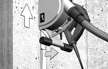
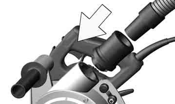
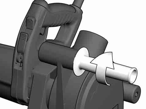
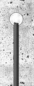
8 STANDARD ø 35 mm START The antistatic hose available as an accessory prevents static charges while vacuuming stone dust. Der im Zubehör erhältliche Antistatikschlauch verhindert statische Aufladungen bei Absaugung von Gestein. Le tuyau flexible antistatique (disponible comme accessoire) évite une accumulation de charges électrostatiques lors de l aspiration de pierre naturelle. Il tubo antistatico, disponibile come accessorio, previene l accumulo di cariche statiche durante l aspirazione di polveri prodotte dalla pietra. La manguera antiestática (disponible como accesorio) elimina la carga estática producida por la aspiración del polvo A mangueira antiestática, que pode ser adquirida como acessório, evita as cargas estáticas durante a aspiração da pedra. De anti-statische slang (leverbaar als extra toebehoren) voorkomt statische lading bij het afzuigen van steenstof. Den antistatiskeslange i tilbehøret forhindrer statisk opladning ved opsugning af sten. Den antistatiske slangen som hører til tilbehøret, hindrer statiske ladingeri avsug og stein. Den antistatiska slang som kan levereras som tillbehör förhindrar statisk laddning vid uppsugning av sten. Antistaattinen letku estää staattisen sähkön latautumisen kivipölyn imuroimisen yhteydessä (saatavissa tarvikkeena). Ï áíôéóôáôéêüò óùëþíáò ðïõ äéáôßèåôáé óôá áîåóïõüñ åìðïäßæåé ôéò óôáôéêýò öïñôßóåéò óå ðåôñþìáôá. Aksesuar olarak alınabilecek anti statik hortum, taş tozunun emilmesi sırasındaki statik yüklenmeyi önler. V příslušenství obsažená antistatická hadice zabraňuje vzniku antistatického náboje při odsávání kamene. V príslušenstve ponúkaná antistatická hadica zabraňuje statickému nabíjaniu pri odsávaní kameňa. Antystatyczny wąż dostępny jako wyposażenie dodatkowe zapobiega tworzeniu się ładunków elektrostatycznych podczas odkurzania pyłu z kamienia. Az antisztatikus csővel (tartozékként kapható) megelőzhetők a statikus töltések a porelszívás közben. Antistatična cev, ki je vsebovana v opremi, preprečuje statično naelektrenje pri odsesavanju kamnin. Antistatična gumena cijev, koja se može dobiti kao pribor, spriječava statične naboje kod usisavanja kamenja. Kā komplektējoša detaļa ir nomērkama antistatistiskā caurule kas pasargā no elektrostatiskas uzlādēšanās, nosūknējot akmens virsmas. Antistatinė žarna, kurią galima įsigyti kaip priedą, užkerta kelią statinėms įkrovoms, siurbiant uolienas. Tarvikuna saadaolev antistaatiline voolik takistab staatilisi laenguid kivimite äraimemisel. Антистатический рукав, имеющийся в числе принадлежностей, предотвращает образование статического заряда во время всасывания каменной пыли. Антистатичният маркуч, който може да се получи като аксесоар, предотвратява статичното наелектризиране при засмукване на праха при шлифоване на камък. Furtunul antistatic disponibil ca accesoriu previne încărcările statice când se aspiră praf de piatră. Антистатските вреќички достапни како аксесоари спречуваат статички електрицитет при собирање камена прав. Антистатичний шланг, який можна замовити зі списку комплектуючих, запобігає утворенню статичного заряду при відсмоктуванні при роботах з каменем. یتوفر الخرطوم المقاوم للكھرباء الاستاتیكیة كجھاز م لحق یمنع الشحنات الاستاتیكیة أثناء كنس الغبار الناتج عن الحجر. ANTISTATIC! AUTOMATIK STOP STOP C C C sec START 14 15


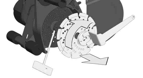
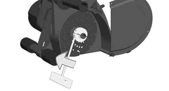
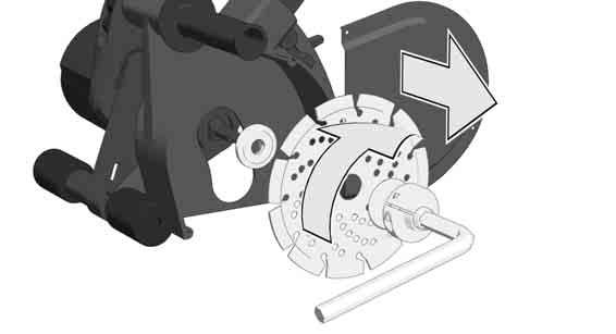
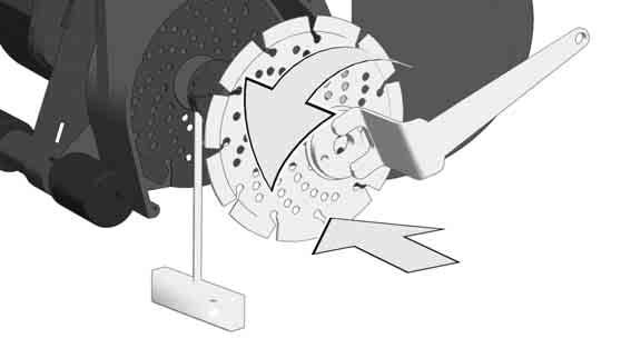
9 1 14 START 2 25 STOP
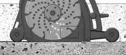
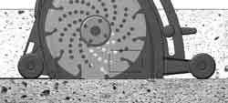
10 TECHNICAL DATA WCS 45 Wall Chaser Production code Rated input 1900 W Rated speed 6200 min -1 D=Diamond cutting disk diameter max. d=hole diameter b=cutting disk thickness min. / max. 150 mm 22,2 mm 2,4 / 2,6 mm Cutting depth 0-45 mm Cutting width mm Weight according EPTA-Procedure 01/2014 6,6 kg Noise/Vibration Information Measured values determined according to EN Typically, the A-weighted noise levels of the tool are: Sound pressure level (K=3dB(A)) 99 db(a) Sound power level (K=3dB(A)) 110 db(a) Wear ear protectors! Vibration total values (triaxial vector sum) determined according to EN Vibration emission value a h,sg 6,5 m/s 2 Uncertainty K 1,5 m/s 2 WARNING The vibration emission level given in this information sheet has been measured in accordance with a standardised test given in EN and may be used to compare one tool with another. It may be used for a preliminary assessment of exposure. The declared vibration emission level represents the main applications of the tool. However if the tool is used for different applications, with different accessories or poorly maintained, the vibration emission may differ. This may signifi cantly increase the exposure level over the total working period. An estimation of the level of exposure to vibration should also take into account the times when the tool is switched off or when it is running but not actually doing the job. This may signifi cantly reduce the exposure level over the total working period. Identify additional safety measures to protect the operator from the effects of vibration such as: maintain the tool and the accessories, keep the hands warm, organisation of work patterns. WARNING! Read all safety warnings and all instructions. Failure to follow the warnings and instructions may result in electric shock, fi re and/or serious injury. Save all warnings and instructions for future reference. CUT-OFF MACHINE SAFETY WARNINGS a) The guard provided with the tool must be securely attached to the power tool and positioned for maximum safety, so the least amount of wheel is exposed towards the operator. Position yourself and bystanders away from the plane of the rotating wheel. The guard helps to protect operator from broken wheel fragments and accidental contact with wheel. b) Use only bonded reinforced or diamond cut-off wheels for your power tool. Just because an accessory can be attached to your power tool, it does not assure safe operation. c) The rated speed of the accessory must be at least equal to the maximum speed marked on the power tool. Accessories running faster than their rated speed can break and fl y apart. d) Wheels must be used only for recommended applications. For example: do not grind with the side of cut-off wheel. Abrasive cut-off wheels are intended for peripheral grinding, side forces applied to these wheels may cause them to shatter. e) Always use undamaged wheel flanges that are of correct diameter for your selected wheel. Proper wheel fl anges support the wheel thus reducing the possibility of wheel breakage. f) Do not use worn down reinforced wheels from larger power tools. Wheels intended for a larger power tool are not suitable for the higher speed of a smaller tool and may burst. g) The outside diameter and the thickness of your accessory must be within the capacity rating of your power tool. Incorrectly sized accessories cannot be adequately guarded or controlled. h) The arbour size of wheels and flanges must properly fit the spindle of the power tool. Wheels and fl anges with arbour holes that do not match the mounting hardware of the power tool will run out of balance, vibrate excessively and may cause loss of control. i) Do not use damaged wheels. Before each use, inspect the wheels for chips and cracks. If power tool or wheel is dropped, inspect for damage or install an undamaged wheel. After inspecting and installing the wheel, position yourself and bystanders away from the plane of the rotating wheel and run the power tool at maximum no load speed for one minute. Damaged wheels will normally break apart during this test time. j) Wear personal protective equipment. Depending on application, use face shield, safety goggles or safety glasses. As appropriate, wear dust mask, hearing protectors, gloves and shop apron capable of stopping small abrasive or workpiece fragments. The eye protection must be capable of stopping fl ying debris generated by various operations. The dust mask or respirator must be capable of fi ltrating particles generated by your operation. Prolonged exposure to high intensity noise may cause hearing loss. k) Keep bystanders a safe distance away from work area. Anyone entering the work area must wear personal protective equipment. Fragments of workpiece or of a broken wheel may fl y away and cause injury beyond immediate area of operation. l) Hold the power tool by insulated gripping surfaces only, when performing an operation where the cutting accessory may contact hidden wiring or its own cord. Cutting accessory contacting a live wire may make exposed metal parts of the power tool live and could give the operator an electric shock. m) Position the cord clear of the spinning accessory. If you lose control, the cord may be cut or snagged and your hand or arm may be pulled into the spinning accessory. n) Never lay the power tool down until the accessory has come to a complete stop. The spinning wheel may grab the surface and pull the power tool out of your control. o) Do not run the power tool while carrying it at your side. Accidental contact with the spinning accessory could snag your clothing, pulling the accessory into your body. p) Regularly clean the power tool s air vents. The motor s fan will draw the dust inside the housing and excessive accumulation of powdered metal may cause electrical hazards. q) Do not operate the power tool near flammable materials. Sparks could ignite these materials. r) Do not use accessories that require liquid coolants. Using water or other liquid coolants may result in electrocution or shock. Further safety instructions for abrasive cutting-off operations Kickback and related warnings Kickback is a sudden reaction to a pinched or snagged rotating wheel. Pinching or snagging causes rapid stalling of the rotating wheel which in turn causes the uncontrolled power tool to be forced in the direction opposite of the wheel s rotation at the point of the binding. For example, if an abrasive wheel is snagged or pinched by the workpiece, the edge of the wheel that is entering into the pinch point can dig into the surface of the material causing the wheel to climb out or kick out. The wheel may either jump toward or away from the operator, depending on direction of the wheel s movement at the point of pinching. Abrasive wheels may also break under these conditions. Kickback is the result of power tool misuse and/or incorrect operating procedures or conditions and can be avoided by taking proper precautions as given below. a) Maintain a firm grip on the power tool and position your body and arm to allow you to resist kickback forces. Always use auxiliary handle, if provided, for maximum control over kickback or torque reaction during start-up. The operator can control torque reactions or kickback forces, if proper precautions are taken. b) Never place your hand near the rotating accessory. Accessory may kickback over your hand. c) Do not position your body in line with the rotating wheel. Kickback will propel the tool in direction opposite to the wheel s movement at the point of snagging. d) Use special care when working corners, sharp edges etc. Avoid bouncing and snagging the accessory. Corners, sharp edges or bouncing have a tendency to snag the rotating accessory and cause loss of control or kickback. e) Do not attach a saw chain, woodcarving blade, segmented diamond wheel with a peripheral gap greater than 10 mm or toothed saw blade. Such blades create frequent kickback and loss of control. f) Do not jam the wheel or apply excessive pressure. Do not attempt to make an excessive depth of cut. Overstressing the wheel increases the loading and susceptibility to twisting or binding of the wheel in the cut and the possibility of kickback or wheel breakage. g) When wheel is binding or when interrupting a cut for any reason, switch off the power tool and hold the power tool motionless until the wheel comes to a complete stop. Never attempt to remove the wheel from the cut while the wheel is in motion otherwise kickback may occur. Investigate and take corrective action to eliminate the cause of wheel binding. h) Do not restart the cutting operation in the workpiece. Let the wheel reach full speed and carefully reenter the cut. The wheel may bind, walk up or kickback if the power tool is restarted in the workpiece. i) Support panels or any oversized workpiece to minimize the risk of wheel pinching and kickback. Large workpieces tend to sag under their own weight. Supports must be placed under the workpiece near the line of cut and near the edge of the workpiece on both sides of the wheel. j) Use extra caution when making a pocket cut into existing walls or other blind areas. The protruding wheel may cut gas or water pipes, electrical wiring or objects that can cause kickback. WALL CHASER & DUST EXTRACTOR TOOL SYSTEM Use only dust extractors for dust class M with the wall chaser. Dust capture and separation may not be as good with other combinations. Observe the instructions for operating, maintaining and cleaning the dust extractor, including the fi lters. Empty the dust container immediately when it becomes full. Use only the designated suction hose. Do not modify the suction hose. If masonry chunks enter the suction hose, stop work and clear the suction hose immediately. Avoid kinking the suction hose. Clean and exchange fi lters regularly. Do not remove any fi lters or fi lter components. Select wall chasers and cutting discs to suit the substrate material. Various types of cutting disc are available for different substrates. Use only diamond-tipped cutting discs. Segmented diamond discs may only be used if they have negative rake and the gap between segments is no wider than 10 mm. Replace or resharpen cutting discs promptly whenever necessary. When cutting performance decreases, check whether the cutting discs are worn and need to be replaced or resharpened. Start and continue grooves as described in the operating instructions. WORKPLACE Ensure compliance with the general requirements for construction work sites (provide adequate lighting, avoid fall hazards, etc.). Follow safety instructions. Ensure good ventilation. Keep the work area clear and unobstructed. With relatively long grooves, the dust extractor must be able to move freely with the chaser and/or travel directly after it. WORK ORGANIZATION Use hearing protection, eye protection, respiratory protection and (if necessary) gloves. At minimum, use a class FFP2 half-face particulate mask for respiratory protection. 18 ENGLISH ENGLISH 19
11 Use a dust extractor to keep the workplace clean. To avoid stirring up dust, do not sweep up dust deposits. TRANSPORT, HANDLING AND STORAGE Diamond cutting discs must be handled and transported with care. Use the original packaging if possible, or use other suitable packaging. Store the discs in a dry location where they are not exposed to mechanical damage. Protect cutting discs against shock, impact and harmful environmental factors. MAINS CONNECTION Connect only to single-phase a.c. current and only to the system voltage indicated on the rating plate. It is also possible to connect to sockets without an earthing contact as the design conforms to safety class II. SPECIFIED CONDITIONS OF USE The wall-chaser machine cuts slots for cables and pipes (masonry grooves) in any kind of brickwork with two diamond cutting discs running parallel to each other. Do not use this product in any other way as stated for normal use. Appliances used at many different locations including wet room and open air must be connected via a residual current device (FI, RCD, PRCD) of 30mA or less. EC-DECLARATION OF CONFORMITY We declare as the manufacturer under our sole responsibility that the product described under Technical Data fulfi lls all the relevant regulations and the directives 2011/65/EU (RoHS), 2014/30/EU, 2006/42/EC, and the following harmonized standards have been used: EN :2009+A11:2010 EN :2011+A11:2013 EN IEC :2021 EN IEC :2021 EN :2019 EN :2013+A1:2019 EN IEC 63000:2018 Winnenden, Alexander Krug Managing Director Authorized to compile the technical fi le. Techtronic Industries GmbH Max-Eyth-Straße Winnenden Germany GB-DECLARATION OF CONFORMITY We declare as the manufacturer under our sole responsibility that the product described under Technical Data fulfi lls all the relevant provisions of the following Regulations S.I. 2008/1597 (as amended), S.I. 2016/1091 (as amended), S.I. 2012/3032 (as amended) and that the following designated standards have been used: BS EN :2009+A11:2010 BS EN :2011+A11:2013 BS EN IEC :2021 BS EN IEC :2021 BS EN :2019 BS EN :2013+A1:2019 BS EN IEC 63000:2018 Winnenden, Alexander Krug Managing Director Authorized to compile the technical file. Techtronic Industries GmbH Max-Eyth-Straße Winnenden Germany ADVICE FOR OPERATION The machine switches off automatically if the motor is overloaded. Allow it to cool, press the overload button and restart the machine. If the overload protection switches it off frequently, reduce the cutting pressure or depth of cut. The infi nitely variable cutting width setting has the advantage that, if the groove width is set correctly, pipes etc. can be fi tted precisely into the groove and it is not necessary to secure them with nails etc. to prevent them from falling out. Sharpen blunt diamond cutting blades (can be recognised by sparks fl ying while cutting) by making several cuts into calcareous sandstone or a special sharpening stone. The cutting discs get very hot when in use. Do not touch them before they have cooled down. MAINTENANCE The ventilation slots of the machine must be kept clear at all times. Use only Milwaukee accessories and spare parts. Should components need to be exchanged which have not been described, please contact one of our Milwaukee service agents (see our list of guarantee/service addresses). If needed, an exploded view of the tool can be ordered. Please state the machine type printed as well as the six-digit No. on the label and order the drawing at your local service agents or directly at: Techtronic Industries GmbH, Max-Eyth-Straße 10, Winnenden, Germany. SYMBOLS CAUTION! WARNING! DANGER! Always disconnect the plug from the socket before carrying out any work on the machine. Please read the instructions carefully before starting the machine. Always wear goggles when using the machine. Wear ear protectors! Use an FFP2 particulate respirator as the minimum amount of protection. Wear gloves! Accessory - Not included in standard equipment, available as an accessory. Do not dispose electric tools, batteries/ rechargeable batteries together with household waste material. Electric tools and batteries that have reached the end of their life must be collected separately and returned to an environmentally compatible recycling facility. Check with your local authority or retailer for recycling advice and collection point. Class II tool, tool in which protection against electric shock does not rely on basic insulation only, but in which additional safety precautions, such as double insulation or reinforced insulation, are provided. There being no provision for protective earthing or reliance upon installation conditions. European Conformity Mark British Confomity Mark Regulatory Compliance Mark (RCM). Product meets applicable regulatory requirements. Ukraine Conformity Mark EurAsian Conformity Mark. 20 ENGLISH ENGLISH 21
12 TECHNISCHE DATEN WCS 45 Mauernutfräse Produktionsnummer Nennaufnahmeleistung 1900 W Nenndrehzahl 6200 min -1 D=Diamanttrennscheiben-ø max. d=bohrungs-ø b=trennscheibendicke min. / max 150 mm 22,2 mm 2,4 / 2,6 mm Schnitttiefe 0-45 mm Schnittbreite mm Gewicht nach EPTA-Prozedur 01/2014 6,6 kg Geräusch/Vibrationsinformation Messwerte ermittelt entsprechend EN Der A-bewertete Geräuschpegel des Gerätes beträgt typischerweise: Schalldruckpegel (K=3dB(A)) 99 db(a) Schallleistungspegel (K=3dB(A)) 110 db(a) Gehörschutz tragen! Schwingungsgesamtwerte (Vektorsumme dreier Richtungen) ermittelt entsprechend EN Schwingungsemissionswert a h 6,5 m/s 2 Unsicherheit K 1,5 m/s 2 WARNUNG Der in diesen Anweisungen angegebene Schwingungspegel ist entsprechend einem in EN genormten Messverfahren gemessen worden und kann für den Vergleich von Elektrowerkzeugen miteinander verwendet werden. Er eignet sich auch für eine vorläufi ge Einschätzung der Schwingungsbelastung. Der angegebene Schwingungspegel repräsentiert die hauptsächlichen Anwendungen des Elektrowerkzeugs. Wenn allerdings das Elektrowerkzeug für andere Anwendungen, mit abweichenden Einsatzwerkzeugen oder ungenügender Wartung eingesetzt wird, kann der Schwingungspegel abweichen. Dies kann die Schwingungsbelastung über den gesamten Arbeitszeitraum deutlich erhöhen. Für eine genaue Abschätzung der Schwingungsbelastung sollten auch die Zeiten berücksichtigt werden, in denen das Gerät abgeschaltet ist oder zwar läuft, aber nicht tatsächlich im Einsatz ist. Dies kann die Schwingungsbelastung über den gesamten Arbeitszeitraum deutlich reduzieren. Legen Sie zusätzliche Sicherheitsmaßnahmen zum Schutz des Bedieners vor der Wirkung von Schwingungen fest wie zum Beispiel: Wartung von Elektrowerkzeug und Einsatzwerkzeugen, Warmhalten der Hände, Organisation der Arbeitsabläufe. WARNUNG! Lesen Sie alle Sicherheitshinweise und Anweisungen. Versäumnisse bei der Einhaltung der Sicherheitshinweise und Anweisungen können elektrischen Schlag, Brand und/oder schwere Verletzungen verursachen. Bewahren Sie alle Sicherheitshinweise und Anweisungen für die Zukunft auf. SICHERHEITSHINWEISE FÜR TRENNSCHLEIFMASCHINEN a) Die zum Elektrowerkzeug gehörende Schutzhaube muss sicher angebracht und so eingestellt sein, dass ein Höchstmaß an Sicherheit erreicht wird, d. h. der kleinstmögliche Teil des Schleifkörpers zeigt offen zur Bedienperson. Halten Sie und in der Nähe befindliche Personen sich außerhalb der Ebene der rotierenden Schleifscheibe. Die Schutzhaube soll die Bedienperson vor Bruchstücken und zufälligem Kontakt mit dem Schleifkörper schützen. b) Verwenden Sie ausschließlich gerade verstärkte oder diamantbesetzte Trennscheiben für Ihr Elektrowerkzeug. Nur weil Sie das Zubehör an Ihrem Elektrowerkzeug befestigen können, garantiert das keine sichere Verwendung. c) Die zulässige Drehzahl des Einsatzwerkzeugs muss mindestens so hoch sein wie die auf dem Elektrowerkzeug angegebene Höchstdrehzahl. Zubehör, das sich schneller als zulässig dreht, kann zerbrechen und umherfl iegen. d) Schleifkörper dürfen nur für die empfohlenen Einsatzmöglichkeiten verwendet werden. Z.B.: Schleifen Sie nie mit der Seitenfläche einer Trennscheibe. Trennscheiben sind zum Materialabtrag mit der Kante der Scheibe bestimmt. Seitliche Krafteinwirkung auf diese Schleifkörper kann sie zerbrechen. e) Verwenden Sie immer unbeschädigte Spannflansche in der richtigen Größe für die von Ihnen gewählte Trennscheibe. Geeignete Flansche stützen die Trennscheibe und verringern so die Gefahr eines Trennscheibenbruchs. f) Verwenden Sie keine abgenutzten Schleifscheiben von größeren Elektrowerkzeugen. Schleifscheiben für größere Elektrowerkzeuge sind nicht für die höheren Drehzahlen von kleineren Elektrowerkzeugen ausgelegt und können brechen. g) Außendurchmesser und Dicke des Einsatzwerkzeugs müssen den Maßangaben Ihres Elektrowerkzeugs entsprechen. Falsch bemessene Einsatzwerkzeuge können nicht ausreichend abgeschirmt oder kontrolliert werden. h) Schleifscheiben und Flansche müssen genau auf die Schleifspindel Ihres Elektrowerkzeugs passen. Einsatzwerkzeuge, die nicht genau auf die Schleifspindel des Elektrowerkzeugs passen, drehen sich ungleichmäßig, vibrieren sehr stark und können zum Verlust der Kontrolle führen. i) Verwenden Sie keine beschädigten Schleifscheiben. Kontrollieren Sie vor jeder Verwendung die Schleifscheiben auf Absplitterungen und Risse. Wenn das Elektrowerkzeug oder die Schleifscheibe herunterfällt, überprüfen Sie, ob es beschädigt ist, oder verwenden Sie eine unbeschädigte Schleifscheibe. Wenn Sie die Schleifscheibe kontrolliert und eingesetzt haben, halten Sie und in der Nähe befindliche Personen sich außerhalb der Ebene der rotierenden Schleifscheibe und lassen Sie das Gerät eine Minute lang mit Höchstdrehzahl laufen. Beschädigte Schleifscheiben brechen meist in dieser Testzeit. j) Tragen Sie persönliche Schutzausrüstung. Verwenden Sie je nach Anwendung Vollgesichtsschutz, Augenschutz oder Schutzbrille. Soweit angemessen, tragen Sie Staubmaske, Gehörschutz, Schutzhandschuhe oder Spezialschürze, die kleine Schleif und Materialpartikel von Ihnen fernhält. Die Augen sollen vor herumfl iegenden Fremdkörpern geschützt werden, die bei verschiedenen Anwendungen entstehen. Staub oder Atemschutzmaske müssen den bei der Anwendung entstehenden Staub fi ltern. Wenn Sie lange lautem Lärm ausgesetzt sind, können Sie einen Hörverlust erleiden. k) Achten Sie bei anderen Personen auf sicheren Abstand zu Ihrem Arbeitsbereich. Jeder, der den Arbeitsbereich betritt, muss persönliche Schutzausrüstung tragen. Bruchstücke des Werkstücks oder gebrochener Einsatzwerkzeuge können wegfl iegen und Verletzungen auch außerhalb des direkten Arbeitsbereichs verursachen. l) Halten Sie das Elektrowerkzeug nur an den isolierten Griffflächen, wenn Sie Arbeiten ausführen, bei denen das Einsatzwerkzeug verborgene Stromleitungen oder das eigene Netzkabel treffen kann. Der Kontakt mit einer spannungsführenden Leitung kann metallene Geräteteile unter Spannung setzen und zu einem elektrischen Schlag führen. m) Halten Sie das Netzkabel von sich drehenden Einsatzwerkzeugen fern. Wenn Sie die Kontrolle über das Elektrowerkzeug verlieren, kann das Netzkabel durchtrennt oder erfasst werden und Ihre Hand oder Ihr Arm in das sich drehende Einsatzwerkzeug geraten. n) Legen Sie das Elektrowerkzeug niemals ab, bevor das Einsatzwerkzeug völlig zum Stillstand gekommen ist. Das sich drehende Einsatzwerkzeug kann in Kontakt mit der Ablagefl äche geraten, wodurch Sie die Kontrolle über das Elektrowerkzeug verlieren können. o) Lassen Sie das Elektrowerkzeug nicht laufen, während Sie es tragen. Ihre Kleidung kann durch zufälligen Kontakt mit dem sich drehenden Einsatzwerkzeug erfasst werden, und das Einsatzwerkzeug sich in Ihren Körper bohren. p) Reinigen Sie regelmäßig die Lüftungsschlitze Ihres Elektrowerkzeugs. Das Motorgebläse zieht Staub in das Gehäuse, und eine starke Ansammlung von Metallstaub kann elektrische Gefahren verursachen. q) Verwenden Sie das Elektrowerkzeug nicht in der Nähe brennbarer Materialien. Funken können diese Materialien entzünden. r) Verwenden Sie keine Einsatzwerkzeuge, die flüssige Kühlmittel erfordern. Die Verwendung von Wasser oder anderen fl üssigen Kühlmitteln kann zu einem elektrischen Schlag führen. Weitere Sicherheitshinweise für Trennschleifanwendungen Rückschlag und entsprechende Sicherheitshinweise Rückschlag ist die plötzliche Reaktion infolge einer hakenden oder blockierten drehenden Schleifscheibe. Verhaken oder Blockieren führt zu einem abrupten Stopp des rotierenden Einsatzwerkzeugs. Dadurch wird ein unkontrolliertes Elektrowerkzeug gegen die Drehrichtung des Einsatzwerkzeugs an der Blockierstelle beschleunigt. Wenn z. B. eine Schleifscheibe im Werkstück hakt oder blockiert, kann sich die Kante der Schleifscheibe, die in das Werkstück eintaucht, verfangen und dadurch die Schleifscheibe ausbrechen oder einen Rückschlag verursachen. Die Schleifscheibe bewegt sich dann auf die Bedienperson zu oder von ihr weg, je nach Drehrichtung der Scheibe an der Blockierstelle. Hierbei können Schleifscheiben auch brechen. Ein Rückschlag ist die Folge eines falschen oder fehlerhaften Gebrauchs des Elektrowerkzeugs. Er kann durch geeignete Vorsichtsmaßnahmen, wie nachfolgend beschrieben, verhindert werden. a) Halten Sie das Elektrowerkzeug gut fest und bringen Sie Ihren Körper und Ihre Arme in eine Position, in der Sie die Rückschlagkräfte abfangen können. Verwenden Sie immer den Zusatzgriff, falls vorhanden, um die größtmögliche Kontrolle über Rückschlagkräfte oder Reaktionsmomente beim Hochlauf zu haben. Die Bedienperson kann durch geeignete Vorsichtsmaßnahmen die Rückschlag und Reaktionskräfte beherrschen. b) Bringen Sie Ihre Hand nie in die Nähe sich drehender Einsatzwerkzeuge. Das Einsatzwerkzeug kann sich beim Rückschlag über Ihre Hand bewegen. c) Meiden Sie den Bereich vor und hinter der rotierenden Trennscheibe. Der Rückschlag treibt das Elektrowerkzeug in die Richtung entgegengesetzt zur Bewegung der Schleifscheibe an der Blockierstelle. d) Arbeiten Sie besonders vorsichtig im Bereich von Ecken, scharfen Kanten usw. Verhindern Sie, dass Einsatzwerkzeuge vom Werkstück zurückprallen und verklemmen. Das rotierende Einsatzwerkzeug neigt bei Ecken, scharfen Kanten oder wenn es abprallt, dazu, sich zu verklemmen. Dies verursacht einen Kontrollverlust oder Rückschlag. e) Verwenden Sie kein Ketten- oder gezähntes Sägeblatt sowie keine segmentierte Diamantscheibe mit mehr als 10 mm breiten Schlitzen. Solche Einsatzwerkzeuge verursachen häufi g einen Rückschlag oder den Verlust der Kontrolle über das Elektrowerkzeug. f) Vermeiden Sie ein Blockieren der Trennscheibe oder zu hohen Anpressdruck. Führen Sie keine übermäßig tiefen Schnitte aus. Eine Überlastung der Trennscheibe erhöht deren Beanspruchung und die Anfälligkeit zum Verkanten oder Blockieren und damit die Möglichkeit eines Rückschlags oder Schleifkörperbruchs. g) Falls die Trennscheibe verklemmt oder Sie die Arbeit unterbrechen, schalten Sie das Elektrowerkzeug aus und halten Sie es ruhig, bis die Scheibe zum Stillstand gekommen ist. Versuchen Sie nie, die noch laufende Trennscheibe aus dem Schnitt zu ziehen, sonst kann ein Rückschlag erfolgen. Ermitteln und beheben Sie die Ursache für das Verklemmen. h) Schalten Sie das Elektrowerkzeug nicht wieder ein, solange es sich im Werkstück befindet. Lassen Sie die Trennscheibe erst ihre volle Drehzahl erreichen, bevor Sie den Schnitt vorsichtig fortsetzen. Anderenfalls kann die Scheibe verhaken, aus dem Werkstück springen oder einen Rückschlag verursachen. i) Stützen Sie Platten oder große Werkstücke ab, um das Risiko eines Rückschlags durch eine eingeklemmte Trennscheibe zu vermindern. Große Werkstücke können sich unter ihrem eigenen Gewicht durchbiegen. Das Werkstück muss auf beiden Seiten abgestützt werden, und zwar sowohl in der Nähe des Trennschnitts als auch an der Kante. j) Seien Sie besonders vorsichtig bei Taschenschnitten in bestehende Wände oder andere nicht einsehbare Bereiche. Die eintauchende Trennscheibe kann beim Schneiden in Gas oder Wasserleitungen, elektrische Leitungen oder andere Objekte einen Rückschlag verursachen. 22 DEUTSCH DEUTSCH 23
13 ARBEITSSYSTEM MAUERNUTFRÄSE - ENTSTAUBER Die Mauernutfräse nur mit den Entstaubern der Staubklasse M einsetzen. Andere Kombinationen können zu einer schlechteren Erfassung und Abscheidung der Stäube führen. Hinweise zum Betrieb, zur Wartung und zur Reinigung des Entstaubers einschließlich der Filter beachten. Wenn Staubsammelbehälter voll sind, sofort entleeren. Nur den vorgesehenen Ansaugschlauch verwenden. Ansaugschlauch nicht manipulieren. Gelangen Gesteinsbrocken in den Ansaugschlauch, Arbeit unterbrechen und den Ansaugschlauch sofort reinigen. Abknicken des Ansaugschlauches vermeiden. Filter regelmäßig abreinigen und austauschen; keine Filter/ Filterkomponenten entfernen. Mauernutfräse und Trennscheiben entsprechend dem Untergrund auswählen. Die Hersteller bieten je nach Untergrund verschiedene Trennscheiben an. Verwenden Sie nur diamantbesetzte Trennscheiben. Segmentierte Diamantscheiben dürfen nur negative Schneidwinkel und maximale Schlitze von 10 mm zwischenden Segmenten aufweisen. Trennscheiben rechtzeitig auswechseln bzw. nachschärfen. Bei Verringerung der Schnittleistung Kontrolle, ob die Trennscheiben verschlissen sind und ausgewechselt bzw. nachgeschärft werden müssen. Eintauchvorgang und Arbeitsablauf, wie in der Bedienungsanleitung beschrieben, durchführen. ARBEITSPLATZ Einhaltung der allgemeinen Anforderungen an Arbeitsplätzen auf Baustellen (ausreichende Beleuchtung, Absturzstellen vermeiden etc.) ist sicherzustellen. Sicherheitshinweise beachten. Für gute Durchlüftung sorgen. Freies Arbeitsfeld gewährleisten. Bei längeren Nuten muss der Entstauber frei nachführbar sein bzw. rechtzeitig nachgeführt werden. ARBEITSORGANISATION Gehörschutz, Augenschutz, Atemschutz und ggf. Handschuhe verwenden. Als Atemschutz mindestens eine Partikel fi ltrierende Halbmaske der Klasse FFP2 verwenden. Entstauber zur Arbeitsplatzreinigung verwenden. Abgelagerten Staub nicht durch Kehren aufwirbeln. TRANSPORT, HANDHABUNG, LAGERUNG Diamanttrennscheiben müssen mit Sorgfalt behandelt und transportiert werden, verwenden sie nach Möglichkeit die Originalverpackung oder eine andere geeignete Verpackung. Die Scheiben müssen in trockener Umgebung so gelagert werden, dass sie keinen mechanischen Beschädigungen ausgesetzt sind. Schützen sie die Trennscheiben vor Schlag und Stoß und schädlichen Umwelteinfl üssen. NETZANSCHLUSS Nur an Einphasen-Wechselstrom und nur an die auf dem Leistungsschild angegebene Netzspannung anschließen. Anschluss ist auch an Steckdosen ohne Schutzkontakt möglich, da ein Aufbau der Schutzklasse II vorliegt. BESTIMMUNGSGEMÄSSE VERWENDUNG Die Mauernutfräse fräst mit zwei parallel laufenden Diamanttrennscheiben Leitungs- und Kabelschlitze (Mauernuten) in jede Art von Mauerwerk. Dieses Gerät darf nur wie angegeben bestimmungsgemäß verwendet werden. Steckdosen in Feuchträumen und Außenbereichen müssen mit Fehlerstrom-Schutzschaltern (FI, RCD, PRCD) ausgerüstet sein. Das verlangt die Installationsvorschrift für Ihre Elektroanlage. Bitte beachten Sie das bei der Verwendung unseres Gerätes. CE-KONFORMITÄTSERKLÄRUNG Wir erklären als Hersteller in alleiniger Verantwortung, dass das unter Technische Daten beschriebene Produkt mit allen relevanten Vorschriften der Richtlinien 2011/65/ EU (RoHS), 2014/30/EU, 2006/42/EG und den folgenden harmonisierten normativen Dokumenten übereinstimmt: EN :2009+A11:2010 EN :2011+A11:2013 EN IEC :2021 EN IEC :2021 EN :2019 EN :2013+A1:2019 EN IEC 63000:2018 Winnenden, Alexander Krug Managing Director Bevollmächtigt die technischen Unterlagen zusammenzustellen Techtronic Industries GmbH Max-Eyth-Straße Winnenden Germany ARBEITSHINWEISE Die Elektronik regelt die Drehzahl bei steigender Belastung nach. Bei längerer Überlastung schaltet die Elektronik auf reduzierte Drehzahl. Die Maschine läuft langsam weiter zum Kühlen der Motorwicklung. Nach Aus- und Wiedereinschalten kann mit der Maschine im Nennlastbereich weitergearbeitet werden. Unter Einwirkung extremer elektromagnetischer Störungen von außen, können im Einzelfall vorübergehende Drehzahlschwankungen auftreten. Stumpfe Diamanttrennscheiben (erkennbar durch starken Funkenfl ug während des Arbeitens) durch mehrere Schnitte in Kalksandstein oder einem speziellen Schärfstein nachschärfen. Die Trennscheiben werden beim Arbeiten sehr heiß; nicht anfassen bevor sie abgekühlt sind. WARTUNG Stets die Lüftungsschlitze der Maschine sauber halten. Nur Milwaukee Zubehör und Ersatzteile verwenden. Bauteile, deren Austausch nicht beschrieben wurde, bei einer Milwaukee Kundendienststelle auswechseln lassen (Broschüre Garantie/Kundendienstadressen beachten). Bei Bedarf kann eine Explosionszeichnung des Gerätes unter Angabe der Maschinen Type und der sechsstelligen Nummer auf dem Leistungsschild bei Ihrer Kundendienststelle oder direkt bei Techtronic Industries GmbH, Max-Eyth-Straße 10, Winnenden, Germany angefordert werden. SYMBOLE ACHTUNG! WARNUNG! GEFAHR! Vor allen Arbeiten an der Maschine Stecker aus der Steckdose ziehen. Bitte lesen Sie die Gebrauchsanweisung vor Inbetriebnahme sorgfältig durch. Beim Arbeiten mit der Maschine stets Schutzbrille tragen. Gehörschutz tragen! Als Atemschutz mindestens eine Partikel fi ltrierende Halbmaske der Klasse FFP2 verwenden. Schutzhandschuhe tragen Zubehör - Im Lieferumfang nicht enthalten, empfohlene Ergänzung aus dem Zubehörprogramm. Elektrogeräte, Batterien/Akkus dürfen nicht zusammen mit dem Hausmüll entsorgt werden. Elektrische Geräte und Akkus sind getrennt zu sammeln und zur umweltgerechten Entsorgung bei einem Verwertungsbetrieb abzugeben. Erkundigen Sie sich bei den örtlichen Behörden oder bei Ihrem Fachhändler nach Recyclinghöfen und Sammelstellen. Elektrowerkzeug der Schutzklasse II. Elektrowerkzeug, bei dem der Schutz vor einem elektrischen Schlag nicht nur von der Basisisolierung abhängt, sondern auch davon, dass zusätzliche Schutzmaßnahmen, wie doppelte Isolierung oder verstärkte Isolierung, angewendet werden. Es gibt keine Vorrichtung zum Anschluss eines Schutzleiters. Europäisches Konformitätszeichen Britisches Konformitätszeichen Regulatory Compliance Mark (RCM). Das Produkt erfüllt die geltenden Vorschriften. Ukrainisches Konformitätszeichen Euroasiatisches Konformitätszeichen 24 DEUTSCH DEUTSCH 25
14 Caractéristiques techniques WCS 45 Rainureuses Murales Numéro de série Puissance nominale de réception 1900 W Vitesse de rotation nominale 6200 min -1 D=ø max. de la meule diamantée d=ø de perçage b=épaisseur disque de coupe min. / max. 150 mm 22,2 mm 2,4 / 2,6 mm Profondeur de coupe 0-45 mm Largeur de coupe mm Poids suivant EPTA-Procedure 01/2014 6,6 kg Informations sur le bruit et les vibrations Valeurs de mesure obtenues conformément à la EN Les mesures réelles (A) des niveaux acoustiques de l appareil sont : Niveau de pression acoustique (Incertitude K=3dB(A)) 99 db(a) Niveau d'intensité acoustique (Incertitude K=3dB(A)) 110 db(a) Toujours porter une protection acoustique! Valeurs totales des vibrations (somme vectorielle de trois sens) établies conformément à EN Valeur d émission vibratoire a h 6,5 m/s 2 Incertitude K= 1,5 m/s 2 AVERTISSEMENT Le niveau vibratoire indiqué dans ces instructions a été mesuré selon un procédé de mesure normalisé dans la norme EN et peut être utilisé pour comparer des outils électriques entre eux. Il convient aussi à une estimation provisoire de la sollicitation par les vibrations. Le niveau vibratoire indiqué représente les applications principales de l outil électrique. Toutefois, si l outil électrique est utilisé pour d autres applications, avec des outils rapportés qui diffèrent ou une maintenance insuffisante, il se peut que le niveau vibratoire diverge. Cela peut augmenter nettement la sollicitation par les vibrations sur tout l intervalle de temps du travail. Pour une estimation précise de la sollicitation par les vibrations, on devrait également tenir compte des temps pendant lesquels l appareil n est pas en marche ou tourne sans être réellement en service. Cela peut réduire nettement la sollicitation par les vibrations sur tout l intervalle de temps du travail. Défi nissez des mesures de sécurité supplémentaires pour protéger l utilisateur contre l infl uence des vibrations, comme par exemple : la maintenance de l outil électrique et des outils rapportés, le maintien au chaud des mains, l organisation des déroulements de travail. AVIS! Lire complètement les instructions et les indications de sécurité. Le non-respect des avertissements et instructions indiqués ci après peut entraîner un choc électrique, un incendie et/ou de graves blessures sur les personnes. Bien garder tous les avertissements et instructions. INDICATIONS DE SÉCURITÉ CONCERNANT LES TRONÇONNEUSES a) Le capot de protection du dispositif électrique doit être fixé d'une façon sûre et il doit être réglé en vue de garantir une sécurité max., c'est-à-dire que la portion de la meule abrasive exposée sans protection vers l'opérateur doit être minimale. L'opérateur et les personnes près de lui ne doivent pas se trouver dans le même plan du disque polisseur. Le capot de protection a le but de protéger l'opérateur des fragments et du contact inattendu avec la meule abrasive. b) Avec le dispositif électrique n'employer que des disques polisseurs renforcés liés ou revêtus en diamant. La simple possibilité de fi xation d'un certain accessoire sur le dispositif électrique ne garantit pas son utilisation en toute sécurité. c) La vitesse assignée de l accessoire doit être au moins égale à la vitesse maximale indiquée sur l outil électrique. Les accessoires fonctionnant plus vite que leur vitesse assignée peuvent se rompre et voler en éclat. d) Les meules doivent être utilisées uniquement pour les applications recommandées. Par exemple : ne pas meuler avec le côté de la meule à tronçonner. Les meules à tronçonner abrasives sont destinées au meulage périphérique, l application de forces latérales à ces meules peut les briser en éclats. e) Utilisez toujours des brides de serrage non détériorées, de la bonne taille, adaptée à la meule que vous avez choisie. Les brides adaptées permettent de protéger la meule et réduisent ainsi le risque de rupture de la meule. f) Ne pas utiliser de meules usées d outils électriques plus grands. La meule destinée à un outil électrique plus grand n est pas appropriée pour la vitesse plus élevée d un outil plus petit et elle peut éclater. g) Le diamètre extérieur et l'épaisseur des outils utilisés doivent correspondre aux cotes de l'outil électrique. Les outils dont la mesure a été effectuée de manière erronée ne peuvent pas être suffisamment blindés ou contrôlés. h) Les disques polisseurs et les brides doivent avoir exactement la même mesure du dispositif électronique. Les accessoires n'ayant pas la même mesure de l'outil de serrage du dispositif électrique tourneront d'une manière déséquilibrée, vibreront d'une manière excessive et ils pourront provoquer la parte de contrôle. i) Ne pas utiliser des disques polisseurs endommagés. Avant chaque utilisation contrôler la présence sur les disques polisseurs d'ébrèchements et de criques. En cas de chute du dispositif électrique ou du disque polisseur, contrôler la présence de dommages ou utiliser un disque polisseur intact. Après avoir contrôlé et monté un disque polisseur, assurez-vous que tant l'opérateur que les autres personnes près de lui ne se trouvent pas dans le même plan du disque polisseur tournant et faire tourner le dispositif pour une minute au nombre max. de tours. Les disques polisseurs endommagés se cassent d'habitude durant cette période d'essai. j) Porter un équipement de protection individuelle. En fonction de l application, utiliser un écran facial, des lunettes de sécurité ou des verres de sécurité. Le cas échéant, utiliser un masque antipoussières, des protections auditives, des gants et un tablier capables d arrêter les petits fragments abrasifs ou des pièces à usiner. La protection oculaire doit être capable d arrêter les débris volants produits par les diverses opérations. Le masque antipoussières ou le respirateur doit être capable de fi ltrer les particules produites par vos travaux. L exposition prolongée aux bruits de forte intensité peut provoquer une perte de l audition. k) Veillez à ce que les personnes tierces respectent une distance sûre par rapport à votre périmètre de travail. Toute personne qui pénètre dans le périmètre de travail doit porter des équipements de protection individuelle. Des fragments de la pièce usinée et d'outils rapportés brisés sont susceptibles de s'envoler et de provoquer des blessures mêmes en dehors du périmètre direct de travail. l) Maintenez l appareil par les surfaces de poignée isolées lorsque vous exécutez des travaux pendant lesquels l outil de coupe peut toucher des lignes électriques dissimulées ou le propre câble. Le contact de l outil de coupe avec un câble qui conduit la tension peut mettre les pièces métalliques de l appareil sous tension et mener à une décharge électrique. m) Placer le câble éloigné de l accessoire de rotation. Si vous perdez le contrôle, le câble peut être coupé ou subir un accroc et votre main ou votre bras peut être tiré dans l accessoire de rotation. n) Ne jamais poser l'appareil électrique avant que l'outil rapporté soit entièrement à l'arrêt. L'outil rapporté en rotation est susceptible d'entrer en contact avec la surface de dépôt, ce qui risquerait de vous faire perdre le contrôle de l'appareil électrique. o) Ne pas faire fonctionner l outil électrique en le portant sur le côté. Un contact accidentel avec l accessoire de rotation pourrait accrocher vos vêtements et attirer l accessoire sur vous. p) Nettoyer régulièrement les orifices d aération de l outil électrique. Le ventilateur du moteur attirera la poussière à l intérieur du boîtier et une accumulation excessive de poudre de métal peut provoquer des dangers électriques. q) Ne pas utiliser l'outil électrique à proximité de matériaux inflammables. Des étincelles sont susceptibles d'enfl ammer ces matériaux. r) Ne pas utiliser d'outils rapportés qui nécessitent des agents réfrigérants liquides. L'utilisation d'eau ou d'autres agents réfrigérants liquides risque de provoquer une électrocution. Ultérieures consignes de sécurité concernant les tronçonneuses Contrecoup et consignes de sécurité correspondantes D'éventuelles contrecoups sont des réactions soudaines causés par des disques polisseurs qui se coincent ou se bloquent pendant leur rotation. D'éventuels coincements ou blocages comportent l'arrêt subit de l'outil. De cette façon un dispositif électrique non contrôle est accéléré, sur le point de blocage, dans la direction opposée à celle de l'outil. Par exemple, si une meule abrasive est accrochée ou pincée par la pièce à usiner, le bord de la meule qui entre dans le point de pincement peut creuser la surface du matériau, provoquant des sauts ou l expulsion de la meule. La meule peut sauter en direction de l opérateur ou encore en s en éloignant, selon le sens du mouvement de la meule au point de pincement. Les meules abrasives peuvent également se rompre dans ces conditions. Le rebond résulte d un mauvais usage de l outil et/ou de procédures ou de conditions de fonctionnement incorrectes et peut être évité en prenant les précautions appropriées spécifi ées cidessous. a) Maintenir fermement l outil électrique et placer votre corps et vos bras pour vous permettre de résister aux forces de rebond. Toujours utiliser une poignée auxiliaire, le cas échéant, pour une maîtrise maximale du rebond ou de la réaction de couple au cours du démarrage. L opérateur peut maîtriser les couples de réaction ou les forces de rebond, si les précautions qui s imposent sont prises. b) Ne jamais placer votre main à proximité de l accessoire en rotation. L accessoire peut effectuer un rebond sur votre main. c) Éviter de stationner devant ou derrière le disque polisseur tournant. Lorsque un contrecoup se produit, le dispositif électrique est poussé dans la direction opposée à celle du mouvement du disque polisseur sur le point de blocage. d) Apporter un soin particulier lors de travaux dans les coins, les arêtes vives etc. Eviter les rebondissements et les accrochages de l accessoire. Les coins, les arêtes vives ou les rebondissements ont tendance à accrocher l accessoire en rotation et à provoquer une perte de contrôle ou un rebond. e) N'utiliser ni lames à chaîne ou à dents, ni lames en diamant segmentées avec fentes dépassant les 10 mm. de largeur. Les types d'outils susdits causent fréquemment d'effets de contrecoup ou la perte de contrôle sur le dispositif électrique. f) Ne pas «coincer» la meule à tronçonner ou ne pas appliquer une pression excessive. Ne pas tenter d exécuter une profondeur de coupe excessive. Une contrainte excessive de la meule augmente la charge et la probabilité de torsion ou de blocage de la meule dans la coupe et la possibilité de rebond ou de rupture de la meule. g) Lorsque la meule se bloque ou lorsque la coupe est interrompue pour une raison quelconque, mettre l outil électrique hors tension et tenir l outil électrique immobile jusqu à ce que la meule soit à l arrêt complet. Ne jamais tenter d enlever la meule à tronçonner de la coupe tandis que la meule est en mouvement sinon le rebond peut se produire. Rechercher et prendre des mesures correctives afi n d empêcher que la meule ne se grippe. h) Ne pas reprendre l opération de coupe dans la pièce à usiner. Laisser la meule atteindre sa pleine vitesse et rentrer avec précaution dans le tronçon. La meule peut se coincer, venir chevaucher la pièce à usiner ou effectuer un rebond si l on fait redémarrer l outil électrique dans la pièce à usiner. i) Prévoir un support de panneaux ou de toute pièce à usiner surdimensionnée pour réduire le risque de pincement et de rebond de la meule. Les grandes pièces à usiner ont tendance à fl échir sous leur propre poids. Les supports doivent être placés sous la pièce à usiner près de la ligne de coupe et près du bord de la pièce des deux côtés de la meule. j) Soyez particulièrement prudent lorsque vous faites une «coupe en retrait» dans des parois existantes ou dans d autres zones sans visibilité. La meule saillante 26 FRANÇAIS FRANÇAIS 27
HD18AG indd
 HD18 AG115 HD18 AG125 Original instructions Originalbetriebsanleitung Notice originale Istruzioni originali Manual original Oorspronkelijke gebruiksaanwijzing Original brugsanvisning Original bruksanvisning
series_155
 RAILING SERIES 155 RIPO fabrika SIA Hanzas Street 2, Pinki, Babite district, LV 2107, Latvia 155 Alumīnija margu sērija Aluminum railing series AL.01 AL.02 AL.03 AL.04 AL.05 AL.06 AL.07 AL.08 AL.09 155
K 5 ( )
") Detaļu saraksts (1.180-633.0) K 5 27.01.2016 www.kaercher.com LV Lapa 2 / 66 Lapa 3 / 66 Lapa 4 / 66 Satura rādītājs Pasūtīšanas norādījumi K 5 (1.180-633.0) Short spare parts list 201 Spare parts list
Detaļu saraksts (1.180-633.0) K 5 27.01.2016 www.kaercher.com LV Lapa 2 / 66 Lapa 3 / 66 Lapa 4 / 66 Satura rādītājs Pasūtīšanas norādījumi K 5 (1.180-633.0) Short spare parts list 201 Spare parts list
State Revenue Services of the Republic Latvia Talejas iela 1, Riga LV-1978 Latvia Ihr Vor- und Zuname Ihre Straße und Hausnummer Ihre Postleitzahl Ihr
 State Revenue Services of the Republic Latvia Talejas iela 1, Riga LV-1978 Latvia Ihr Vor- und Zuname Ihre Straße und Hausnummer Ihre Postleitzahl Ihr Wohnort aktuelles Datum Ihre ZINSPILOT-Kundennummer
Art.Nr Art.Nr. AusgabeNr AusgabeNr. Rev.Nr /04/2015 Rev.Nr. 28/06/2017 HG34 DE Doppelschleifer Origin
 Art.Nr. 5906103924 Art.Nr. AusgabeNr. 5903106901 5906103851 AusgabeNr. Rev.Nr. 5903106851 16/04/2015 Rev.Nr. 28/06/2017 HG34 DE Doppelschleifer Originalbetriebsanleitung 8-16 NO Benkslipemaskin Oversettelse
K1000S.indd
 K 1000 S Original instructions Originalbetriebsanleitung Notice originale Istruzioni originali Manual original Oorspronkelijke gebruiksaanwijzing Original brugsanvisning Original bruksanvisning Bruksanvisning
Mounting_Instruction_Owl_Class_II_High_Bay_
 VIZULO OWL LED high bay Mounting instruction Montāžas instrukcija Mонтажная инструкция IEC EN 60598 IP66 min 40 C max + 50 C (+45 C)* 198-264 V AC * Depends on configuration. Check label or technical specification.
7. Tēma: Polinomi ar veseliem koeficientiem Uzdevums 7.1 (IMO1982.4): Prove that if n is a positive integer such that the equation x 3 3xy 2 + y 3 = n
: Prove that if n is a positive integer such that the equation x 3 3xy 2 + y 3 = n") 7. Tēma: Polinomi ar veseliem koeficientiem Uzdevums 7.1 (IMO1982.): Prove that if n is a positive integer such that the equation x xy 2 + y = n has a solution in integers x, y, then it has at least three
7. Tēma: Polinomi ar veseliem koeficientiem Uzdevums 7.1 (IMO1982.): Prove that if n is a positive integer such that the equation x xy 2 + y = n has a solution in integers x, y, then it has at least three
/8 10/2018 EL 340 EL 380 EL 420 IT BG BS CS DA DE EL EN ES ET FI FR HR HU LT LV MK NL NO Tosaerba elettrico con conducente a piedi MANUALE DI
 171505669/8 10/2018 EL 340 EL 380 EL 420 IT BG BS CS DA DE EL EN ES ET FI FR HR HU LT LV MK NL NO Tosaerba elettrico con conducente a piedi MANUALE DI ISTRUZIONI ATTENZIONE: prima di usare la macchina,
SNP3000_UM_LV_2.2.indd
 Register your product and get support at www.philips.com/welcome Philips Presenter SNP3000 LV Lietotāja rokasgrāmata 1 a b c d e g f h 2 3 4 LASER LIGHT DO NOT STARE INTO BEAM CLASS 2 LASER PRODUCT Wavelength
Mēbeļu piedāvājums / Office furniture offer
 Mēbeļu piedāvājums / Office furniture offer Ovāls pārrunu galds 1 - kļava, 1 - tumši pelēks Uz divām mono-kājām (nerūs.tērauds) 200cm virsmas garums, 90cm virsmas platums, 75cm augstums Skaits - 2 Cena
/5 02/2019 E300 E320 E380 IT BG BS CS DA DE EL EN ES ET FI FR HR HU LT LV MK NL NO Tosaerba elettrico con conducente a piedi MANUALE DI ISTRU
 171505829/5 02/2019 E300 E320 E380 IT BG BS CS DA DE EL EN ES ET FI FR HR HU LT LV MK NL NO Tosaerba elettrico con conducente a piedi MANUALE DI ISTRUZIONI ATTENZIONE: prima di usare la macchina, leggere
/8 10/2018 EL 340 EL 380 EL 420 IT BG BS CS DA DE EL EN ES ET FI FR HR HU LT LV MK NL NO Tosaerba elettrico con conducente a piedi MANUALE DI
 171505669/8 10/2018 EL 340 EL 380 EL 420 IT BG BS CS DA DE EL EN ES ET FI FR HR HU LT LV MK NL NO Tosaerba elettrico con conducente a piedi MANUALE DI ISTRUZIONI ATTENZIONE: prima di usare la macchina,
KURSA KODS
 Lappuse 1 no 5 KURSA KODS STUDIJU KURSA PROGRAMMAS STRUKTŪRA Kursa nosaukums latviski Kursa nosaukums angliski Kursa nosaukums otrā svešvalodā Studiju /-as, kurai/-ām tiek piedāvāts studiju kurss Statuss
1. pielikums Papildu pakalpojumi Appendix 1 Additional Services 1. Pārvadātājs sniedz Papildu pakalpojumus, kas papildina vai paplašina Transporta pak
 1. pielikums Papildu pakalpojumi Appendix 1 Additional Services 1. Pārvadātājs sniedz Papildu pakalpojumus, kas papildina vai paplašina Transporta pakalpojumu nosacījumus. Papildu pakalpojumi attiecas
book
 ZERO TURN MOWER series Type 991313 RIDING ROTARY LAWN MOWER SAMOJÍZDNÁ SEKAČKA AUFSITZ-SICHELMÄHER HAVETRAKTOR MED ROTERENDE KNIVE TRACTOR CORTACÉSPED GIRATORIO KETASNIIDUKIGA MURUTRAKTOR PUUTARHATRAKTORI
Microsoft Word - AT2018_sakums_MAKETS_ docx
 Latvijas Republikas Senāta spriedumi un lēmumi 2018. Rīga: Tiesu namu aģentūra, 2019. 1037 lpp. (VII, A 401, C 351, K 275) Krājumu sagatavoja: Latvijas Republikas Senāta Administratīvo lietu departamenta
Art.Nr / AusgabeNr Rev.Nr. 22/11/2017 HP1100S / HP1300S D GB FR IT Rüttelplatte Original-Anleitung Vibratory Plates
 Art.Nr. 5804603984 / 5804604984 AusgabeNr. 5804602851 Rev.Nr. 22/11/2017 HP1100S / HP1300S D GB FR IT Rüttelplatte Original-Anleitung Vibratory Plates Translation from the original instruction manual Plaque
FVO 204 INSTALLATION ET MISE EN SERVICE FRANÇAIS INSTALLATION AND STARTING INSTRUCTIONS ENGLISH INSTALLAZIONE E MESSA IN SERVIZIO ITALIANO INSTALACIÓN
 FVO 204 INSTALLATION ET MISE EN SERVICE FRANÇAIS INSTALLATION AND STARTING INSTRUCTIONS ENGLISH INSTALLAZIONE E MESSA IN SERVIZIO ITALIANO INSTALACIÓN Y INSTRUCCIONES DE PUESTA EN MARCHA ESPAÑOL N.M.S.
Art.Nr AusgabeNr Rev.Nr. 12/07/2017 HL850 DE GB CZ SK HU Holzspalter Originalbetriebsanleitung Log splitter Translation from t
 Art.Nr. 5905306903 AusgabeNr. 5905306850 Rev.Nr. 12/07/2017 HL850 DE GB CZ SK HU Holzspalter Originalbetriebsanleitung Log splitter Translation from the original instruction manual Štípačka na dřevo Překlad
pro-fra.p p65
 p r o e q u i p m e n t Mode d emploi CM 1200/11/500 D SILENT SDS N de cde. 25469 CE www.contimac.be IT Conservare questo manuale d istruzioni per poterlo consultare in futuro GB Preserve this handbook
Art.Nr /2014 SG4500 D GB FR Stromgenerator Original-Betriebsanleitung Electric generator Original Operating Instru
 Art.Nr. 5906207901 5906207903 5906207850 11/2014 SG4500 D GB FR Stromgenerator Original-Betriebsanleitung Electric generator Original Operating Instructions Groupe électrogène Traduction de la notice originale